
B-Line series Cable Tray Design Considerations
Our wind certification report provides you with list of acceptable B-Line series cable tray supports, fittings and covers based off of the environmental conditions, cable loading, and type of cable tray in your
Cable Tray Sleeper Design Details
The document provides details on the design of a cable tray mechanical support system, including specifications for cable tray sleepers, impeded steel plates, and concrete foundations.
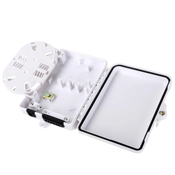
Wire Basket Tray System
Powder coated tray requires the removal of the coating in the clamping area in order to create a bond. Cable tray should be bonded to the building or facility grounding system every 50'' – 60''.
Cable Tray Technical Guide A practical guide to product selection
Cable tray length is selected based on the load to be supported, the distance between the supports (also referred to as the span), and handling and installation constraints.
Complete cable tray manual for electrical engineers and
Complete cable tray manual for electrical engineers and designers
Drawings | Innovative Cable Trays, Cable Management
Download Snake Tray drawings detailing our innovative cable trays, cable management, and power distribution solutions. We sweat the details!
Guide to cable support systems
The load capacity of the cable trays according to the support width can be read off in the diagram using load curves – here, shown as an example for a cable tray with the tray widths 100 to 600 mm.
CABLE TRAY SYSTEMS GUIDE
Some applications may require the cable tray to support the weight of a single, dead object in addition to the cable loads. Specifications typically require this to be applied at the midpoint of the span between
Complete cable tray manual for electrical engineers and designers
Complete cable tray manual for electrical engineers and designers (on photo: power cable management ladder tray systems assembled aluminum cable tray ladder for building cabling projects; credit:
Concept Cable tray drawing | PDF
This document contains a drawing list for cable tray layouts on multiple floors of a building. It includes the drawing number, size, date, and revision details for drawings of cable tray layouts on the ground,

INSTALLATION GUIDE
If the span between the tray supports is less than the length of the straight section (Diagram D.7.B), place the tray across both supports so that the ends are cantilevered.
Optical Power Meters & Sources
High-precision power meters (Ge/InGaAs) and stabilized light sources for insertion loss and return loss testing.
OTDR & Fiber Characterization
Full-featured OTDR, fiber OTDR testers, and modular OTDR test modules for network deployment and troubleshooting.
OSA & Eye Diagram Analyzer
High-resolution OSA for DWDM and eye diagram testers for signal integrity validation.
BERT & Endface Inspection
BERT up to 800G, fiber endface inspection probes, and extinction ratio meters for comprehensive testing.