lecture13_ee620_tias
Finite bandwidth amplifier modifies the transimpedance transfer function to a second-order low-pass function
Transimpedance Amplifier Calculator
Understanding the behavior of transimpedance amplifiers is crucial for engineers and hobbyists working with optical sensing applications. This guide explores the principles behind
Transimpedance Amplifier Calculator
Enter the photodiode current, output voltage, or feedback resistor into the calculator to compute the missing value. Transimpedance Amplifier Calculator
CIRCUIT0020 Design tool | TI
View the TI CIRCUIT0020 Design tool downloads, description, features and supporting documentation and start designing.
Transimpedance Amplifier Calculator: Master Precision Design!
This article will delve into the fundamental principles that govern Transimpedance Amplifiers, providing a solid theoretical foundation before exploring practical design considerations
Op-Amp Transimpedance Amplifier
A transimpedance amplifier (TIA) converts a current to a voltage and is often used with current-based sensors like photodiodes. It''s also a common building block that helps explain the performance and

What you need to know about transimpedance amplifiers part 1
You can find an Excel calculator incorporating the equations and theory described in this post here. If you are designing a TIA, be sure to check the calculator out.
Online Simulation of a Transimpedance Amplifier Circuit
Online Simulation of the Transimpedance Amplifier Circuit. This fast photodiode transimpedance amplifier is based on a high- speed JFET- input op

A Wideband Transimpedance Amplifier
The goal of Part I of this project is to analyze and optimize the given BJT transimpedance amplifier architecture (see appendix for schematic). We began by identifying the main stages of the TIA and
High Speed Amps Roadmap
In this case we are starting with a source capacitance a target bandwidth and an amplifier and seeing how high a transimpedance gain we can get, then we compute the input-referred noise, integrating

Wideband Trans-impedance Amplifier Design
Trans-impedance amplifier is an important block at the input of an optical receiver. They are an integral part of optical fiber receivers because they must sense the current produced by a
The Design of a Transimpedance Amplifier [The Analog Mind]
This calculation suggests that the voltage at the source of M2 must be shifted down before reaching the gate of M1 . This can be accomplished by a CG stage, as illustrated in Fig-ure 8(b).
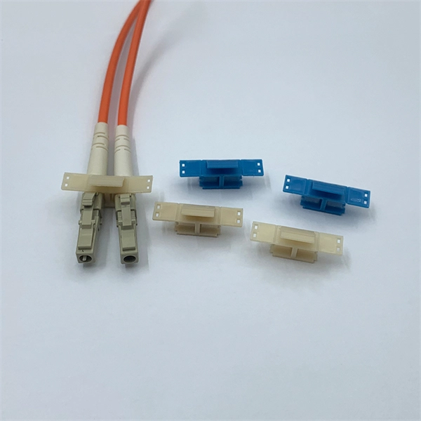
Optical Power Meters & Sources
High-precision power meters (Ge/InGaAs) and stabilized light sources for insertion loss and return loss testing.
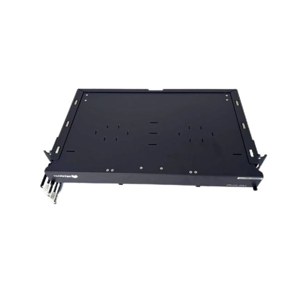
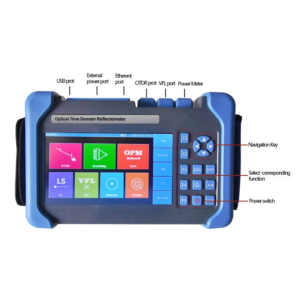
OTDR & Fiber Characterization
Full-featured OTDR, fiber OTDR testers, and modular OTDR test modules for network deployment and troubleshooting.
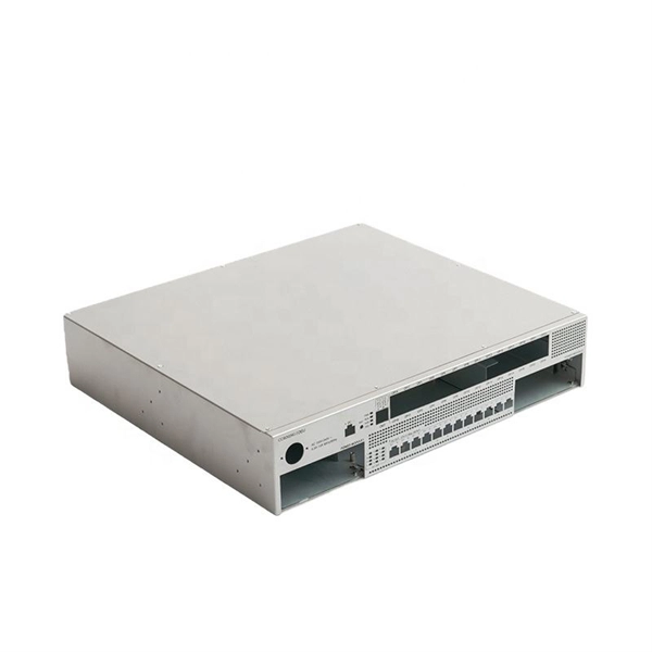
OSA & Eye Diagram Analyzer
High-resolution OSA for DWDM and eye diagram testers for signal integrity validation.
BERT & Endface Inspection
BERT up to 800G, fiber endface inspection probes, and extinction ratio meters for comprehensive testing.