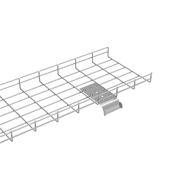
Cable tray and cable management NEMA catalog
It is typically more cost effective to use an Aluminum or Pre-Galvanized Steel cable tray and paint it after installation, along with the other un-painted building components.
Cable Tray Installation Guidelines | PDF | Galvanization
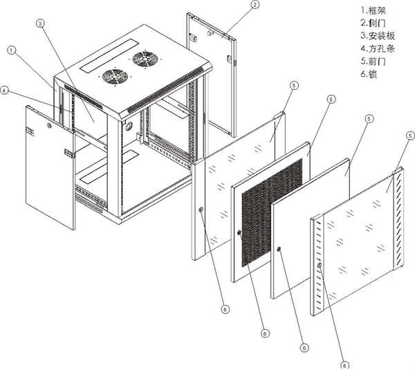
This document provides details on installing cable trays and their support systems. It includes diagrams showing how to mount cable trays on walls using pre-fabricated flanges or channels.
B-Line series Cable Tray Design Considerations
Our wind certification report provides you with list of acceptable B-Line series cable tray supports, fittings and covers based off of the environmental conditions, cable loading, and type of cable tray in your
Method Statement installation of Cable Trays and Ladders
This method statement covers the site installation of the cable tray & ladders and the requirements of checks to be carried out.
26 05 36 Cable Trays for Electrical Systems
Fasten and support cables that pass from one cable tray to another or drop from cable trays to equipment enclosures. Fasten cables to the cable tray at the point of exit and support cables
GUIDE CABLE TRAYS TECHNICAL
When fitting cable trays and their accessories, the products are cut on site to create changes of direction, adjust sections, etc. Damage can also occur during handling; as a result, both the
CABLE TRAY SYSTEMS GUIDE
The Ladder Tray features light, rugged, tubular steel construction. It is designed for mechanical support and strain relief in long runs of cable and creates a smooth gradual bend for cable.
Cable Tray Technical Guide A practical guide to product selection
Cable tray length is selected based on the load to be supported, the distance between the supports (also referred to as the span), and handling and installation constraints.
A Guide to Installing and Supporting Electrical Cable Trays
This guide covers the critical steps, from selecting the right electrical cable tray and performing accurate cable fill calculations to managing a safe cable pull through and ensuring all bonding and grounding
Instrumentation Cable Tray Installation Checklist and
Step-by-step instrumentation cable tray installation guide with safety tips, standards, inspections, and downloadable Excel checklist.
Cable Tray Installation Method Statement
Ensure the gaps between the trays which are mounted in tires are sufficient for the cable laying as per the approved installation details drawings. Cable Ladder and Cable Tray Installation Steps After the
Fittings LONG SP
Solid bottom tray shall incorporate two side rails connected by solid steel metal. Ladder shall consist of two side-rails with rungs riveted to the bottom flange of the side-rails. rungs shall be spaced 8” or 12”
Optical Power Meters & Sources
High-precision power meters (Ge/InGaAs) and stabilized light sources for insertion loss and return loss testing.
OTDR & Fiber Characterization
Full-featured OTDR, fiber OTDR testers, and modular OTDR test modules for network deployment and troubleshooting.
OSA & Eye Diagram Analyzer
High-resolution OSA for DWDM and eye diagram testers for signal integrity validation.
BERT & Endface Inspection
BERT up to 800G, fiber endface inspection probes, and extinction ratio meters for comprehensive testing.