Cable Tray Installation Procedure Guide | PDF
It describes inspecting and storing cable trays upon receipt, installing trays flat or vertically, fixing trays to structures, designing trays to carry loads, providing
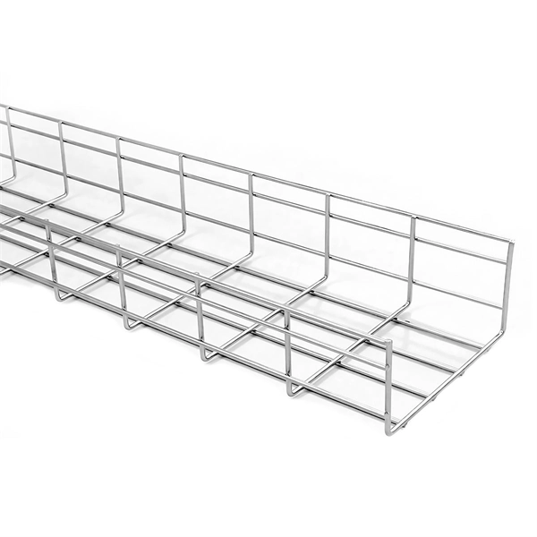
Cable Tray Technical Guide A practical guide to product selection
In designing supports for a cable tray system, consideration should be given to the loads associated with future cable additions and any additional loading that may be applied to the cable tray system (e.g.,
INSTALLATION GUIDE
An elevation benchmark (preferably set by the general contractor) can be transferred via laser level or transit to convenient points along the length of the tray run.
5 Steps to Learn How to Install Cable Trays
Installing a cable tray system requires careful planning to ensure it can support the weight of the cables and adheres to electrical safety codes. Here is a step-by-step guide on how to install a

Cable Tray Installation Procedure Guide | PDF | Electrical Wiring
It describes inspecting and storing cable trays upon receipt, installing trays flat or vertically, fixing trays to structures, designing trays to carry loads, providing covers in areas with risk of damage, allowing
SECTION 26 05 36 CABLE TRAYS FOR ELECTRICAL
Designer shall provide a 12” vertical working clearance above the cable tray with no continuous obstructions. In addition, a 12” space must be provided on either side for working access.
Mastering Cable Tray Installation | Step-by-Step Guide for a Seamless
Mastering cable tray installation is crucial for creating a safe, organised, and efficient cable management system. By following this step-by-step guide, you can ensure a seamless setup that
A Guide to Installing and Supporting Electrical Cable Trays
This guide covers the critical steps, from selecting the right electrical cable tray and performing accurate cable fill calculations to managing a safe cable pull through and ensuring all bonding and grounding
B-Line series Cable Tray Design Considerations
Most outdoor cable tray systems are ladder type tray, and the most severe wind loading will be the impact pressure to the cable tray side rails. The generic impact pressures corresponding to various
Cable Tray | Design Master Software Docs
Starting Elevation: The starting elevation of the cable tray. The reference point for the starting elevation of the cable tray is set by the Vertical Alignment . Visit the Elevation section for more information.
To Change the Elevation of a Cable Tray or Conduit Run
Check your cable tray or conduit run to find out if you need to add more segments or change the elevation of other segments in order to reconnect the run. Optionally connect segments by adding

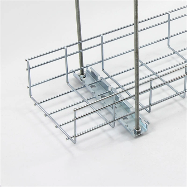
Cablofil: How to Change Elevation in Wire Mesh Tray
Learn how to reinforce changes in elevation for heavy power cables using the EAC Kit. All hardware needed for installation is supplied. For more information,...
Optical Power Meters & Sources
High-precision power meters (Ge/InGaAs) and stabilized light sources for insertion loss and return loss testing.
OTDR & Fiber Characterization
Full-featured OTDR, fiber OTDR testers, and modular OTDR test modules for network deployment and troubleshooting.
OSA & Eye Diagram Analyzer
High-resolution OSA for DWDM and eye diagram testers for signal integrity validation.
BERT & Endface Inspection
BERT up to 800G, fiber endface inspection probes, and extinction ratio meters for comprehensive testing.