Fiber Splice Loss Calculator | MFD Mismatch & Alignment
Splice loss occurs whenever the mode fields of two joined fibers do not perfectly overlap. In single-mode fibers, light travels as a Gaussian beam. This tool uses the Marcuse Gaussian Approximation to

What Is the Acceptable Splice Loss in Optical Fiber?
Acceptable splice loss in optical fiber is typically considered to be less than 0.1 dB for fusion splices and less than 0.3 dB for mechanical splices; however, this can vary depending on the
Understanding Fiber Loss: What Is It and How to Calculate It?
This post introduces the main fiber loss types, the calculation process of link loss including fiber attenuation, connector loss, and splice loss, calculating power budget and calculating

Guidelines On What Loss To Expect When Testing
The cable plant "loss budget" is a function of the losses of the components in the cable plant - fiber, connectors and splices, plus any passive optical components

Optical Fiber Loss and Attenuation | MEETOPTICS Academy
Insertion loss, also referred to as connector losses, refers to the loss of optical power that occurs when light is transmitted through a component, such as a connector, splice, coupler, or any other device
Fiber Optic Loss Calculator
Estimate fiber attenuation, connector loss, splice loss, and budget margin for links. Compare wavelengths, distances, safety reserves, receiver limits, and operating headroom accurately.
Fiber Optic Loss Explained: Measurement, Impact, and
Splice loss is introduced where two fiber ends are permanently joined. Because splices appear repeatedly throughout access networks, their
What is the standard for splice loss in optical fiber?
The acceptable splice loss levels in optical fiber installations vary depending on the type of fiber being used and the specific application. However, as a general rule, the splice loss should be as low as

Guidelines On What Loss To Expect When Testing Fiber Optic Cables
The cable plant "loss budget" is a function of the losses of the components in the cable plant - fiber, connectors and splices, plus any passive optical components like splitters in PONs.
Multimode Splice Loss
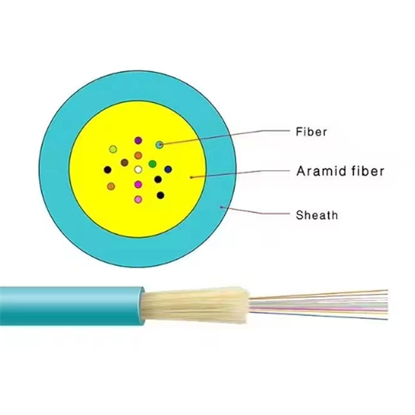
Fiber misalignment is a byproduct of the splicing process and can occur with any splice. Even when splicing identical fibers together, if they are not perfectly aligned, optical power will be lost and
Fiber Optic Loss Explained: Measurement, Impact, and Control in Optical
Splice loss is introduced where two fiber ends are permanently joined. Because splices appear repeatedly throughout access networks, their cumulative impact is substantial. From a
What is Optical Fibre Splice Loss?
When it comes to splicing fiber optic cable, the splice loss in optical fiber is controlled by two main parameters: intrinsic splice loss and extrinsic splice loss.
Optical Power Meters & Sources
High-precision power meters (Ge/InGaAs) and stabilized light sources for insertion loss and return loss testing.
OTDR & Fiber Characterization
Full-featured OTDR, fiber OTDR testers, and modular OTDR test modules for network deployment and troubleshooting.
OSA & Eye Diagram Analyzer
High-resolution OSA for DWDM and eye diagram testers for signal integrity validation.
BERT & Endface Inspection
BERT up to 800G, fiber endface inspection probes, and extinction ratio meters for comprehensive testing.