SINGLE BAND 4T4R OPENRADIO RRU
After the power cable and optical fiber confirm that the link is normal, the power-on test status is normal, indicating that the device can work normally, then close the small window cover and tighten it with
HUAWEI RRU3908 V1 INSTALLATION MANUAL Pdf Download
Strip the jacket of the DC RRU power cable for a small part, press the exposed shielding layer on the strap, and then connect the PGND cable on the strap to the nearest grounding bolt on the side in the

Cellular Network Infrastructure: From Antenna to BBU
Connectivity to BBU: The RRU connects to the BBU through a bi-directional fiber optic link, usually using the Common Public Radio Interface (CPRI). This high-speed link ensures low
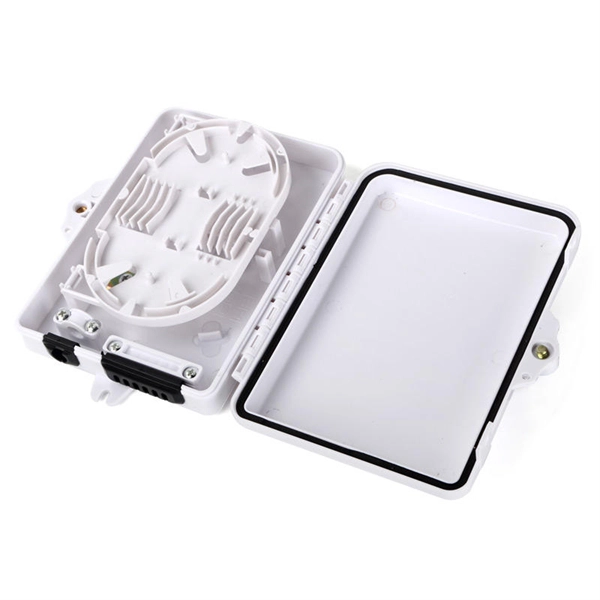
Exhibit 8 Manuals
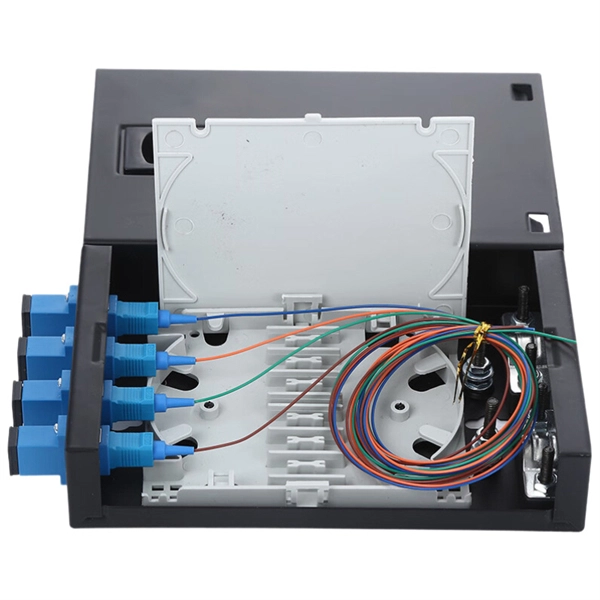
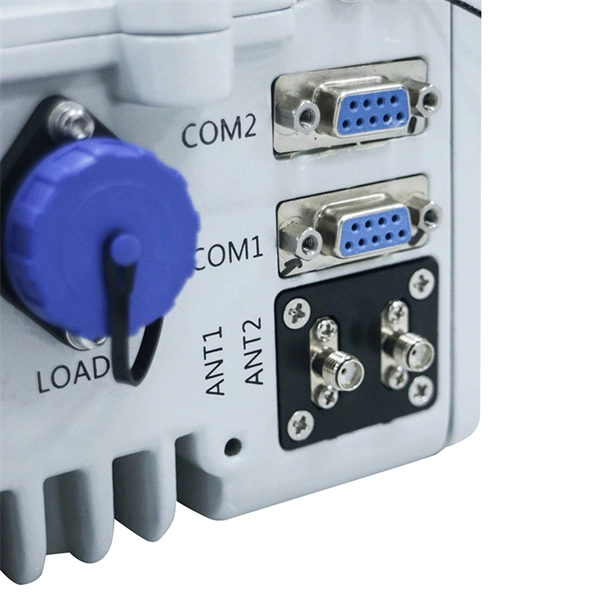
The 1 and 2 interfaces provide connections to optical cables for traffic and timing signals between the RRU and the main unit. A Small Form-Factor Pluggable (SFP) is used to connect the optical cable to

HUAWEI RRU3971 INSTALLATION MANUAL Pdf
Do not stand an RRU upright because the RF ports cannot support the weight of the RRU. l Place a foam pad or cardboard under an RRU to protect the RRU housing
Microsoft PowerPoint
After the cables are installed on the RRU, insert the waterproofing fillers into the idle cable holes. When wrapping the waterproofing tape, apply even force to extend the tape until the width of the tape is 1/2
eRRU Quick Installation Guide (V100R005C10_04) (PDF)-EN.pdf
Connect the M6 OT terminal at one end of the PGND cable to the ground terminal at the bottom of the eRRU and the M8 OT terminal at the other end to the external ground bar.
Ericsson RBS 3418 Product Description
Optical cables must be installed from the Main Unit and RRU to the dark fiber network and then connected to a single fiber pair in the network. The connection is normally made by the transmission
RRU Installation and Hardware Guide
It describes the appearance and functions of the RRU, and outlines the steps for installing the RRU units, connecting the power and optical cables, and properly grounding the equipment.
Huawei Technologies Remote Radio Unit : User''s Manual
After you unpack an RRU, power it on within 24 hours. If you power off the RRU for maintenance, restore it to power within 24 hours. Figure 10-1 shows the RRU power-on check process. PAGE 98

Connecting the RRU AAU Optical Cable
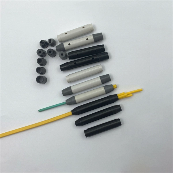
Open the outdoor quick-lock fiber optic connector, and you can see the fiber optic cable on the active connector. The active connector plugs into the optical module on the AAU.
Installation Guide
Before hoisting fiber optic cables onto the tower, connect the fiber optic cables to the RRU or BBU based on the labels on both ends of the cables and determine the hoisting direction.
Optical Power Meters & Sources
High-precision power meters (Ge/InGaAs) and stabilized light sources for insertion loss and return loss testing.
OTDR & Fiber Characterization
Full-featured OTDR, fiber OTDR testers, and modular OTDR test modules for network deployment and troubleshooting.
OSA & Eye Diagram Analyzer
High-resolution OSA for DWDM and eye diagram testers for signal integrity validation.
BERT & Endface Inspection
BERT up to 800G, fiber endface inspection probes, and extinction ratio meters for comprehensive testing.