A Guide to Installing and Supporting Electrical Cable Trays
This guide covers the critical steps, from selecting the right electrical cable tray and performing accurate cable fill calculations to managing a safe cable pull through and ensuring all bonding and grounding
Cable Tray Load Calculation Guide
The document summarizes the load calculations for various structural elements of a building, including: 1) Cable tray loads accounting for the weight and number of
Cable Tray Supports | McMaster-Carr
Choose from our selection of cable tray supports in a wide range of styles and sizes. Same and Next Day Delivery.
Vertical Support
This Vertical Support elevates the cable tray off the floor to allow for free air flow. Easily snaps on to pedestal supports.
Cable Tray Technical Guide A practical guide to product selection
In designing supports for a cable tray system, consideration should be given to the loads associated with future cable additions and any additional loading that may be applied to the cable tray system (e.g.,
Best Practice Guide to Cable Ladder and Cable Tray Systems
This publication is intended as a practical guide for the proper and safe* installation of cable ladder systems, cable tray systems, channel support systems and associated supports.
CABLE TRAY SYSTEMS GUIDE
The total load supported by the cable tray, uniformly distributed. This will be the combined weight of all of the cables or tray contents, any environmental loads (snow, ice, dust) and any concentrated static
Guide to cable support systems
The load capacity of the cable trays according to the support width can be read off in the diagram using load curves – here, shown as an example for a cable tray with the tray widths 100 to 600 mm.
Document DICOS
To install the cable tray supports, first find the required elevation from the floor to the bottom of the cable tray and establish a level line with a laser or a nylon string.
B-Line series Cable Tray Design Considerations
Our wind certification report provides you with list of acceptable B-Line series cable tray supports, fittings and covers based off of the environmental conditions, cable loading, and type of cable tray in your
GUIDE CABLE TRAYS TECHNICAL
Galvanic corrosion must be taken into account within the whole cable management system and makes it essential to choose the right supports, accessories (coupling, screws, equipotential bonding, etc).
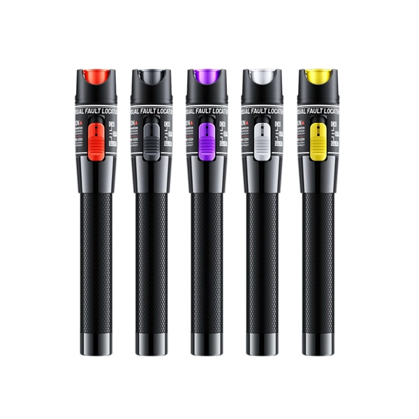
Optical Power Meters & Sources
High-precision power meters (Ge/InGaAs) and stabilized light sources for insertion loss and return loss testing.
OTDR & Fiber Characterization
Full-featured OTDR, fiber OTDR testers, and modular OTDR test modules for network deployment and troubleshooting.
OSA & Eye Diagram Analyzer
High-resolution OSA for DWDM and eye diagram testers for signal integrity validation.
BERT & Endface Inspection
BERT up to 800G, fiber endface inspection probes, and extinction ratio meters for comprehensive testing.