
Marshalling Cabinet drawing and its significance
Marshalling cabinet diagram will aid an Instrumentation Engineer or technician to install, commission and troubleshoot the interface between field devices and control system IO cards. This
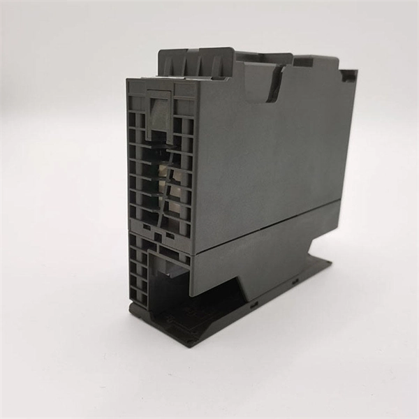
Interface Modules and System Wiring | WAGO
Wire individual components of your equipment quickly, easily and systematically – whether for automation, or at the interconnection point between control cabinet wiring and a standard interface
PLC Cabinet Connection Guide: Industrial Automation Connectors,
Learn how to connect a PLC cabinet to industrial machines using heavy-duty connectors. Discover modular wiring solutions for faster maintenance and reliable automation systems.

PLC Wiring: From Field Instrument to System Cabinet
These internal wires go from the Marshalling Cabinet to the System Cabinet, where the I/O cards are installed. This setup keeps the wiring organized and makes maintenance easier.

Inside a DCS Rack: Understanding the Different Modules
This diagram visualizes the complete signal flow: from field sensors through input modules to the controller, and from the controller through output modules to the final control elements.
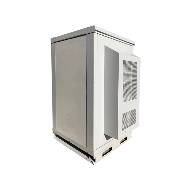
Guide to PLC Cabinets: Types, Layout, Wiring
This guide will walk you through the essential steps to design and wire an efficient PLC control cabinet. We''ll cover key topics like selecting components,
Instrumentation Marshalling cabinet
The marshalling cabinet acts as an interface between the system cabinet and field junction boxes. The main cables are laid from the field junction boxes to the marshalling cabinet.
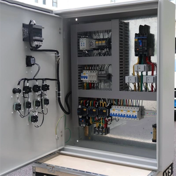
Marshalling Cabinet: Definition, Types, Applications
In simple terms, a marshalling cabinet acts as an interface point where field cables are grouped, cross-wired, and connected to system cables, improving wiring clarity, flexibility, and maintenance efficiency.
Understanding Marshalling Cabinets
The document discusses the purpose and function of a marshalling cabinet in an industrial automation system. A marshalling cabinet interfaces field cables carrying input and output signals with
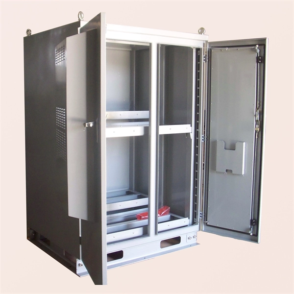
What is Marshalling Cabinet ?
Marshalling CabinetCabinet TypesCommon MistakesElectronic Marshalling CabinetsDedicated Marshalling CabinetsClosure View of Marshalling Cabinet ComponentsPoints to take care during the design stage when using dedicated marshalling cabinets: 1. All the wires from field multi-pair/core cables should be terminated in marshalling cabinets. Change in cable type (e.g. 16 pair to 24 pair) would have increase terminals inside the marshalling cabinet. 2. Change in junction box grouping will have little impac...See more on instrumentationtools instrumentationedu
Marshalling Cabinet: Definition, Types, Applications
In simple terms, a marshalling cabinet acts as an interface point where field cables are grouped, cross-wired, and connected to system cables, improving wiring
What is Marshalling Cabinet ?
This marshalling cabinet function is to interface the incoming field cable (which is normally a multipair cable) and the I/O (Input/Output) card connection.
Guide to PLC Cabinets: Types, Layout, Wiring & Components
This guide will walk you through the essential steps to design and wire an efficient PLC control cabinet. We''ll cover key topics like selecting components, cabinet layout, cooling, wiring, and
Optical Power Meters & Sources
High-precision power meters (Ge/InGaAs) and stabilized light sources for insertion loss and return loss testing.
OTDR & Fiber Characterization
Full-featured OTDR, fiber OTDR testers, and modular OTDR test modules for network deployment and troubleshooting.
OSA & Eye Diagram Analyzer
High-resolution OSA for DWDM and eye diagram testers for signal integrity validation.
BERT & Endface Inspection
BERT up to 800G, fiber endface inspection probes, and extinction ratio meters for comprehensive testing.