ITER Electrical Design Handbook Earthing and Lightning Protection
As far as possible, the lightning protection conductors placed on top of or nearby outdoor equipment will be directly connected earthing rods (minimum length and cross-sections are defined at 8.7.1).
Transmission Line Grounding Guide
The purpose of this grounding guide is to provide useful, practical information applicable to de-signing effective grounding systems for electric transmission lines to: (1) manage steady state and fault
Harger Lightning & Grounding
Harger provides a design which allows the current, either lightning or electrical fault, to maintain a downward sloping path to ground. Most manufacturers utilize a design which forces lightning to go
BY ORDER OF THE AIR FORCE MANUAL 32-1065
A sketch of the grounding and lightning protection system is provided showing test point and where services enter the facility. The sketch should also show the location of the probes during the ground
Grounding System Installation Standards for Distribution Boxes and
Whether you''re a seasoned pro or just starting out, this comprehensive guide will give you practical insights into proper grounding techniques, with a special focus on how selecting quality materials

LIGHTNING PROTECTION AND GROUNDING
If a distribution circuit is added to subtransmission pole with 7-#10 Copperweld or #6 Cu. pole ground wire and the static wire is used for the distribution system neutral, the pole ground wire must be
LPI-175 / 2023 Edition
In special circumstances where lightning cannot be allowed to penetrate, the use of tall masts and overhead ground wires used in a reduced zone model can provide additional protection.
eCFR :: 46 CFR Part 111 Subpart 111.05 -
Circuits are grounded to limit excessive voltage from lightning, transient surges, and unintentional contact with higher voltage lines, and to limit the voltage to ground during normal operation.

Distribution System Grounding
It provides guidance on grounding electrode systems, lightning protection, and communications grounding and serves as a reference guide for computer room signal.
Best Practice in Lightning Protection for Distribution Systems
For systems located in high lightning regions, the neutral is also grounded where line arresters are installed. The most common distribution system configurations are 4-wire solidly
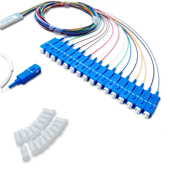
Optical Power Meters & Sources
High-precision power meters (Ge/InGaAs) and stabilized light sources for insertion loss and return loss testing.
OTDR & Fiber Characterization
Full-featured OTDR, fiber OTDR testers, and modular OTDR test modules for network deployment and troubleshooting.
OSA & Eye Diagram Analyzer
High-resolution OSA for DWDM and eye diagram testers for signal integrity validation.
BERT & Endface Inspection
BERT up to 800G, fiber endface inspection probes, and extinction ratio meters for comprehensive testing.