NEC Requirements for Sizing Junction Boxes and Pull Boxes
A pull box contains a 2-in. and a 3-in. raceway on the left side, a 3-in. raceway on the top, and a 2-in. raceway on the right side. The 2-in. raceways are a straight pull and the 3-in. raceways
Pull Box Sizing : A Comprehensive Guide for Engineers
Proper sizing of pull boxes is essential to ensure safe, code-compliant, and maintainable electrical installations. This guide provides a practical breakdown of pull box sizing rules as per NEC Article
314.28 Pull and Junction Boxes and Conduit Bodies.
Use the angle pull image to help answer the question. When installing insulated conductors of 4 AWG or larger, the minimum dimensions of pull or junction boxes
How to Install an Electrical Pull Box: NEC Rules & Sizing
A professional guide to sizing and installing electrical pull boxes and junction boxes for straight, angle, and U pulls, according to NEC 314.28.
Pull Boxes and Junction Boxes
Pull boxes, junction boxes, and conduit bodies must be sized to allow conductors 4 AWG and larger to be installed without damage to the conductor insulation. The NEC provides sizing requirements in
NEC Pull Box Sizing Guide for Electrical Code Compliance
Learn how to size NEC pull boxes correctly with code references, real-world examples, and expert tips—ensure compliance and reduce costly installation errors.
NEC Junction and Pull Box Sizing Guide | PDF | Electric Power
It provides the key rules for sizing boxes based on conductor sizes of 4 AWG and larger, including minimum dimensions for straight pulls, angle pulls, U pulls, and splices. It also discusses the
Don''t Fail Inspection: NEC Rules for Pull & Junction Boxes.
Electrical installations demand strict adherence to the National Electrical Code (NEC). Understanding the NEC is essential for safe and compliant work, especially when dealing with
314.28 Pull and Junction Boxes and Conduit Bodies. Angle Pulls, U
Use the angle pull image to help answer the question. When installing insulated conductors of 4 AWG or larger, the minimum dimensions of pull or junction boxes installed in a raceway or cable run must

Pull and Junction Boxes and Conduit Bodies | UpCodes
The section outlines requirements for pull and junction boxes and conduit bodies, emphasizing compliance with specific standards. It details minimum size criteria for boxes housing conductors of 4
A Complete Guide to NEC Article 314 on Electrical Boxes and Conduit
The wiring method used determines which cables appear inside boxes. In residential work, NM-B cable is most common, but other wiring methods may be present if these are not
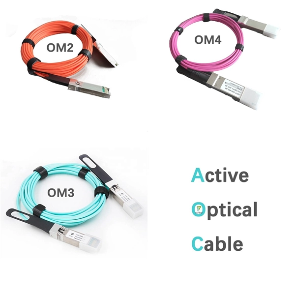
Optical Power Meters & Sources
High-precision power meters (Ge/InGaAs) and stabilized light sources for insertion loss and return loss testing.
OTDR & Fiber Characterization
Full-featured OTDR, fiber OTDR testers, and modular OTDR test modules for network deployment and troubleshooting.
OSA & Eye Diagram Analyzer
High-resolution OSA for DWDM and eye diagram testers for signal integrity validation.
BERT & Endface Inspection
BERT up to 800G, fiber endface inspection probes, and extinction ratio meters for comprehensive testing.