A Comprehensive Guide to Jointing Busbars: Which Method is Best
Cleaning and roughing of the surface areas before assembling the joint is effective at minimizing this. In some cases, adding a filler such as petroleum jelly around the contact to block oxygen penetration

Copper Busbar Jointing Methods
Bolted joints are formed by overlapping the bars and bolting through the overlap area. They are compact, reliable and versatile but have the disadvantage that holes must be drilled or

Injection Lap Riveting of Aluminum Busbars—A Thermo-Electro
The process is based on the extension of injection lap riveting to the connection of busbars made from the same material as the rivets and requires redesigning the joints to ensure complete filling with
Long-term behaviour of bare, bolted busbar joints
Several variables afect this resistance, which increases with time because of aging. The heat losses rise at the same time. Ultimately, excessive heating can lead to total failure of the joint. Service life can

Optimal Busbar Joint Overlap
What is the optimal busbar joint overlap? The minimum overlap should be from 8 to 10 times the busbar thickness.

Electric performance of hybrid busbar joints under service and high
Classification of the main joining technologies to fabricate lap joints in hybrid busbars made from copper and aluminum laminated sheets or bars with some examples of processes.
A Comprehensive Guide to Jointing Busbars: Which
Cleaning and roughing of the surface areas before assembling the joint is effective at minimizing this. In some cases, adding a filler such as petroleum jelly around the
Busbar Joints
Bolting pattern is an important aspect of the joint design if the overlap area is large and more than one fixing is required to reach the required contact force.

Copper Busbar Joint Overcurrent: Key Issues and Engineering Solutions
Industry trends indicate the overcurrent issue at copper busbar lap joints has become a critical bottleneck for new energy development, urging innovative solutions.
Copper Busbar Joint Overcurrent: Key Issues and
Industry trends indicate the overcurrent issue at copper busbar lap joints has become a critical bottleneck for new energy development, urging
Title (size 40)
Joining by forming process without auxiliary elements that generates high contact pressures along the overlapping area. The assembly process can be carried out in progressive tool systems comprising a
Effect of connection design on the contact resistance of high
The contact resistance measurements were carried out on the connector-pad/busbar combinations whose contacting surfaces were given different surface finish: as received, brushed, brushed and
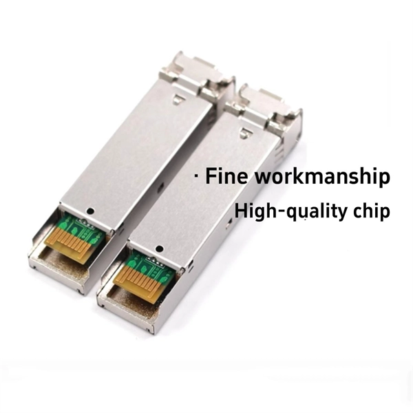
Optical Power Meters & Sources
High-precision power meters (Ge/InGaAs) and stabilized light sources for insertion loss and return loss testing.
OTDR & Fiber Characterization
Full-featured OTDR, fiber OTDR testers, and modular OTDR test modules for network deployment and troubleshooting.
OSA & Eye Diagram Analyzer
High-resolution OSA for DWDM and eye diagram testers for signal integrity validation.
BERT & Endface Inspection
BERT up to 800G, fiber endface inspection probes, and extinction ratio meters for comprehensive testing.