How to Calculate Fiber Loss | Optical Attenuation Explained
Optical fiber loss is a term for signal loss affecting transmission reliability. Therefore, it is very important to calculate the fiber loss and take appropriate steps. This article provides insights
Guidelines On What Loss To Expect When Testing
The uncertainty of the loss test is probably in the same range, so the actual loss is in the range of 7.7 to 8.7dB. Thus there is considerable overlap of the loss budget
Fiber Optic Cable Failures in the Field And How to Prevent Them
Exposure to extremes of heat or cold, or rapid temperature fluctuations, can cause expansion and contraction in the cable materials, leading to stress on the fiber.
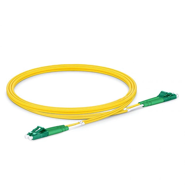
How to reduce the joint loss when the single -mode optical fiber jump
However, this joint can result in a loss of signal due to various factors, including misalignment of the fibers and excess or insufficient melting of the fibers. In this article, we will
Fbb Calculator
By entering these values, users can instantly determine the total loss for a fiber optic link, enabling better system design, troubleshooting, and maintenance planning.
Fiber Joints – connectors, alignment tolerances, coupling loss, single
With the fiber optics software RP Fiber Calculator PRO, one can conveniently calculate coupling losses at misaligned fiber joints. For more sophisticated demands, one may use RP Fiber Power.
Guidelines On What Loss To Expect When Testing Fiber Optic Cables
The uncertainty of the loss test is probably in the same range, so the actual loss is in the range of 7.7 to 8.7dB. Thus there is considerable overlap of the loss budget and the measurement results, so there
Fiber alignment and joint loss | PPT
This document discusses optical losses associated with fiber optic joints. It describes losses from Fresnel reflection at the interface between fibers due to differences in refractive index.
Factors affecting fiber splice loss and how to reduce it
Fiber splice loss is caused by core mismatch, contamination, and misalignment. Reduce loss with proper cleaning, alignment, and splicing techniques.
Tutorial Passive Fiber Optics, Part 6: Fiber Joints
A critical aspect of fiber optics is the joining of optical fibers, ensuring efficient light transfer from one fiber to another. This article delves into the various types of fiber joints, coupling losses, and the intricacies
Understanding Fiber-Optic Cable Signal Loss, Attenuation, and
To determine the power budget and power margin needed for fiber-optic connections, you need to understand how signal loss, attenuation, and dispersion affect transmission.
Optical Power Meters & Sources
High-precision power meters (Ge/InGaAs) and stabilized light sources for insertion loss and return loss testing.
OTDR & Fiber Characterization
Full-featured OTDR, fiber OTDR testers, and modular OTDR test modules for network deployment and troubleshooting.
OSA & Eye Diagram Analyzer
High-resolution OSA for DWDM and eye diagram testers for signal integrity validation.
BERT & Endface Inspection
BERT up to 800G, fiber endface inspection probes, and extinction ratio meters for comprehensive testing.