
Fiber Optic System Testing Tutorial
Patch cords or equipment jumpers are used to bridge the network electronic ports to the fiber optic link contained between patch panels (also known as “cross-connects”). Figure 1 below

The FOA Reference For Fiber Optics
In an installed cable plant, one must test the entire cable from end to end, including every component in it, such as splices, couplers, and connectors intermediate patch panels.

Fiber Optic Polarity 101: A-B Polarity
A duplex patch cord with A-B polarity carries a "straight-through" position, as seen in the example below. When facing an open port in the "Keyup" position, "B" will always be on the left and "A" will always be
How to Properly Test the Insertion Loss of Fiber Optic Patch Cords?
Therefore, it is essential to test the insertion loss of fibre optic patch cords to ensure optimal network performance. This article will guide you through the process of testing the...
BYU Photonics
Fiber Optic Connectors FC Connector Diagram Fiber Patch Cords Standard Corning Optical Fibers
How to Test Fiber Optic Patch Cords
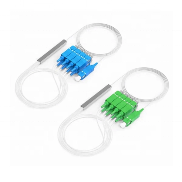
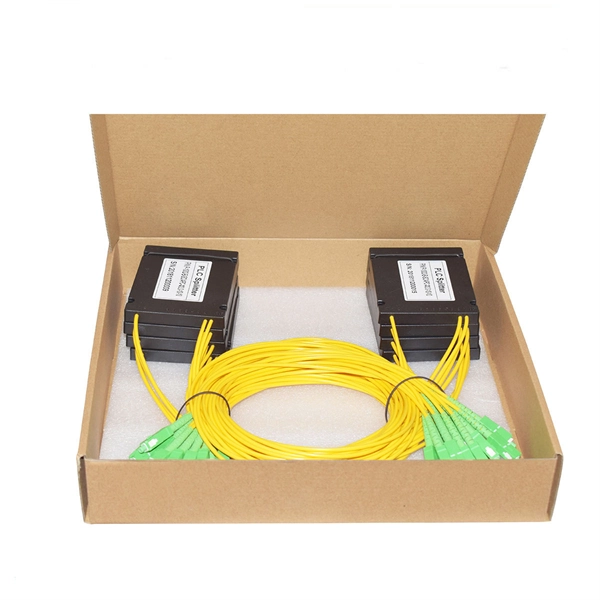
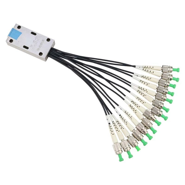
Fiber optic patch cord is an optical transmission line connects fiber optic devices or fiber optic networks, it consists of two fiber optic connectors and a fiber optic cable. Quality of the patch cord has a direct
How to Make a Fiber Optic Patch Cord Step by Step
Learn how to make a fiber optic patch cord step by step, from preparation to testing, for reliable high-performance connections.
Testing The Patch Cord
"Channel test" is the whole combined cabling circuit and chained with patch cord, wall plate, horizontal cable, patch panel, and patch cord. The maximum length for this combined cabling circuit is 100m.
How to Test Patch Cords and Fiber Jumpers
A copper patch cord and fiber jumper connection test was conducted to see which brands can consistently pass industry standards. See the results here.
Permanent Link Testing of Multimode and Singlemode Fiber
This document describes how and where permanent link loss testing should be performed based on the specifics of the cabling system. A link loss equation is used to calculate acceptable attenuation
The FOA Reference For Fiber Optics
After fiber optic cables are installed, spliced and terminated, they must be tested. For every fiber optic cable plant, you need to test for continuity and polarity, end-to-end insertion loss and then
Optical Power Meters & Sources
High-precision power meters (Ge/InGaAs) and stabilized light sources for insertion loss and return loss testing.
OTDR & Fiber Characterization
Full-featured OTDR, fiber OTDR testers, and modular OTDR test modules for network deployment and troubleshooting.
OSA & Eye Diagram Analyzer
High-resolution OSA for DWDM and eye diagram testers for signal integrity validation.
BERT & Endface Inspection
BERT up to 800G, fiber endface inspection probes, and extinction ratio meters for comprehensive testing.