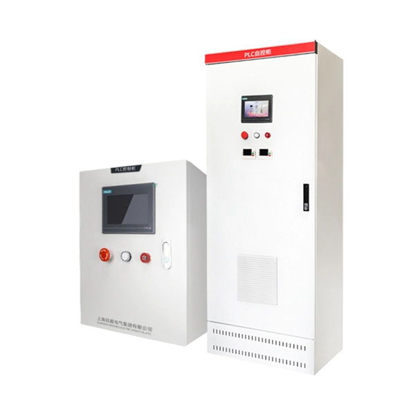
Keep on Running—Select Motor Relay Settings to Balance
In this paper, we discuss the need to maximize motor usage and illustrate steps needed to set the trip and reset settings for motor thermal protection. The time to reset after a normal stop, overload, or trip
Start and Stall protection of Induction Motor
If a start is sensed by the relay through monitoring current and/or start device closure, but the speed switch does not operate, the relay element uses the safe stall time setting to trip the motor before
Motor Overload Relay Setting: The 125% Rule Explained
Authoritative guidance on setting motor overload relays to 125% of nameplate FLA, explaining the rationale, practical calculation methods, and common pitfalls in motor protection.
Motor Protection Theory
The motor thermal limits curves, Figure 9, consist of three distinct segments, which are based on the three running conditions of the motor: the locked rotor or stall condition, motor acceleration and
How to Calculate Motor Protection Relay Settings Step by Step
Calculate thermal overload, overcurrent, ground fault, and differential relay settings with step-by-step examples. Covers CT ratios and common mistakes.

Motor Protection Relay Setting Guide
Under such a condition, if the relay had the Start Inhibit feature enabled, the relay would lock-out the motor start until the thermal capacity of the motor had dropped
AC Motor Protection
If a start is detected by the protection relay through monitoring current and/or start device closure, but the speed switch does not operate, the protection relay element uses the safe stall time setting to trip
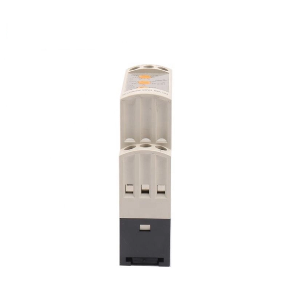
CSM_EPSC_PS_TG_E_2_3
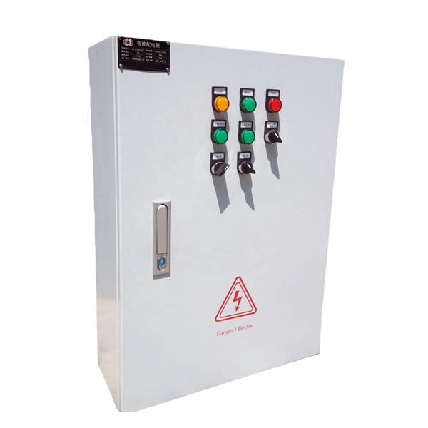
The overload protection feature of the 3E Relay protects the motor from overload when it operates normally. With this feature alone, the motor can be protected most of the time.
Functions and Principles of Motor Stall Protection
During stalling, current can reach 5-7 times the rated value, rapidly generating high temperatures that damage insulation or burn coils. The moter protection relay promptly cuts off the
Overload Relays Current Setting: Expert Guide for Electricians
Overload relays current settings are vital to protect motors from damage. Learn how to match current ratings and set trip settings for thermal protection.
Motor Protection Relay Setup Guide | PDF | Electric
The document discusses how to set the protective relay for a motor based on its datasheet specifications and system configuration.
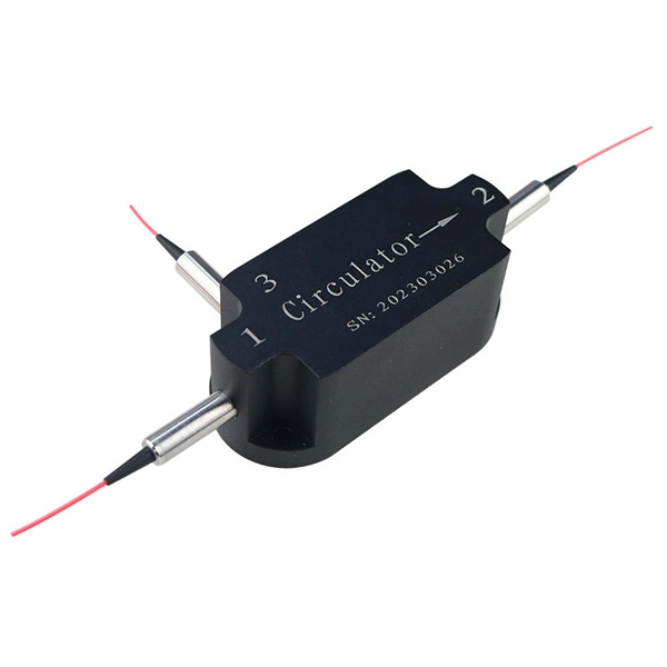
Optical Power Meters & Sources
High-precision power meters (Ge/InGaAs) and stabilized light sources for insertion loss and return loss testing.
OTDR & Fiber Characterization
Full-featured OTDR, fiber OTDR testers, and modular OTDR test modules for network deployment and troubleshooting.
OSA & Eye Diagram Analyzer
High-resolution OSA for DWDM and eye diagram testers for signal integrity validation.
BERT & Endface Inspection
BERT up to 800G, fiber endface inspection probes, and extinction ratio meters for comprehensive testing.