Fiber Optic Color Code: Complete Guide 2026
Efficient fiber optic engineering depends on accurate identification. Installers use color codes to terminate cables rapidly, patch systems correctly, and ensure continuity between panels and splice
The Complete Step-by-Step Guide to Fiber Optic Splicing
In this guide, we cover the basics of fiber optic splicing, how to perform splicing using two different methods, and finally some best practices to perform good fiber splicing.
Fiber Optic Splicing Types, Methods, and Applications Explained
Fiber optic splicing involves joining two fiber optic cables to create a continuous optical path. This is typically done when the cable length is insufficient or when the fiber network is damaged and needs

Fiber Optic Splicing Color Codes Guide
Fiber Optic Splicing Color Codes Guide This document describes different fiber optic cable configurations: 1) A 24 fiber cable with 4 fibers per tube or 6 fibers per tube
Fiber Optic Testing Standards
If splicing is to be done, route and coil the fiber as just explained, then after spliced, land the splice into the manifold in its correct position according to color code.
Fiber Optic Color Code: The Ultimate TIA-598-C Guide
Since the earliest days of fiber optics, multimode cables have typically been color‑coded orange, black, or gray, while single‑mode cables are marked in yellow.

How do fiber experts know what colour of fiber to splice to
When you splice a color to another color it''s normally because you''re splicing in a lateral or an Mid cable access. These are essentially T''s where it no longer makes sense to do it color to color as you''re
How to Splice Fiber Optic Pigtails: A Step-by-Step Guide
Master the art of fiber termination. Learn how to splice fiber optic pigtails using fusion splicing, follow the color code, and ensure low insertion loss.
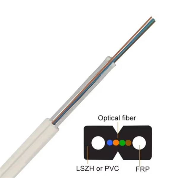
Color Arrangement Rules For Optical Fiber
The color arrangement for optical fiber cables is standardized to ensure consistent identification of individual fibers during installation, splicing, and maintenance.
Fiber Optic Color Codes
When a fiber optic tech splices cables, makes terminations behind patch panels or selects patch cords to interconnect cables or connect electronic equipment, they use color codes, defined by the
Optical Power Meters & Sources
High-precision power meters (Ge/InGaAs) and stabilized light sources for insertion loss and return loss testing.
OTDR & Fiber Characterization
Full-featured OTDR, fiber OTDR testers, and modular OTDR test modules for network deployment and troubleshooting.
OSA & Eye Diagram Analyzer
High-resolution OSA for DWDM and eye diagram testers for signal integrity validation.
BERT & Endface Inspection
BERT up to 800G, fiber endface inspection probes, and extinction ratio meters for comprehensive testing.