METHOD STATEMENT FOR CABLE TRAY AND
This procedure to clear the method of the supply, installations Cable Tray and Trunking System for the project.
Cable Tray Technical Guide A practical guide to product selection
The choice of method should be discussed with a local inspector. The best decision may be to extend only the cables, creating a discontinuity in the cable tray.
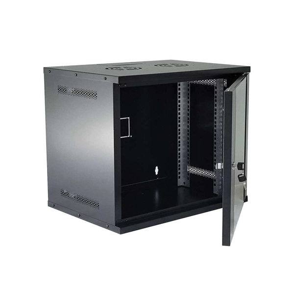
CABLE TRAY
In order to install the cable tray supports, first find the required elevation from the floor to the bottom of the cable tray and establish a level line with a laser or a nylon string.
Method Statement For Installation Of Cable Tray
Only approved and undamaged cable trays and accessories (e.g., bends, tees, reducers, covers, supports, hangers, bolts) shall be used for installation.
Cable Tray Installation Method Statement | PDF | Cable
This document provides a method statement for installing cable trays and trunking systems for building electrical services.
Cable Tray Ladder Trunking Wire Basket Installation Guidelines
It should be mounted far enough off the floor or roof to allow the cables to exit through the bottom of the cable tray. If a strut is used for this purpose, mount the strut directly to the floor or roof and attach the
CABLE TRAY SYSTEMS GUIDE
Some applications may require the cable tray to support the weight of a single, dead object in addition to the cable loads. Specifications typically require this to be applied at the midpoint of the span between
Best Practice Guide to Cable Ladder and Cable Tray Systems
This publication is intended as a practical guide for the proper and safe* installation of cable ladder systems, cable tray systems, channel support systems and associated supports.
Document DICOS
Attaching a channel cable tray by using the method illustrated in Figure 3-88 maintains the electrical requirements, and the bolted mechanical connection while providing a practical method for dropping
Configuration methods A – Quiklok tray – Conne
Bend side wires on both sides of the tray and reassemble using adjustable clamps to attach side rail edge and universal splices to attach tray bottoms. To form a horizontal cross, proceed in the same
A Guide to Installing and Supporting Electrical Cable Trays
This guide covers the critical steps, from selecting the right electrical cable tray and performing accurate cable fill calculations to managing a safe cable pull through and ensuring all bonding and grounding
NEC Article 392: Cable Tray Systems
It provides rules for acceptable wiring methods that can be installed in cable trays, including conditions for use. It addresses uses permitted and not permitted for cable trays.
Optical Power Meters & Sources
High-precision power meters (Ge/InGaAs) and stabilized light sources for insertion loss and return loss testing.
OTDR & Fiber Characterization
Full-featured OTDR, fiber OTDR testers, and modular OTDR test modules for network deployment and troubleshooting.
OSA & Eye Diagram Analyzer
High-resolution OSA for DWDM and eye diagram testers for signal integrity validation.
BERT & Endface Inspection
BERT up to 800G, fiber endface inspection probes, and extinction ratio meters for comprehensive testing.