An Introduction to Protective Relays for Solar-Plus-Storage Systems
In this article, we''ll explain how protective relays work, review some of the most common relay functions for solar and energy storage systems, and provide best practices for relay
ProtectionofDistribution CircuitswithHighPenetrationof SolarPV
Our open-loop tests included a TD21 relay, and another feeder/DER protection relay that implements device numbers 50, 51, 46, 47, and 67, along with other functions not evaluated for DER protection.

SPDTableOfContents.qxd
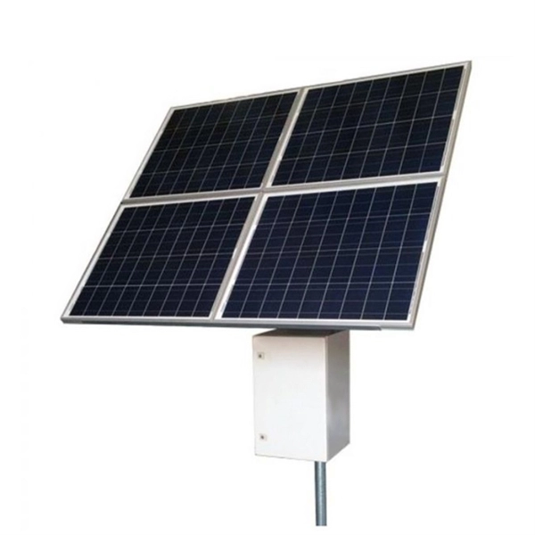
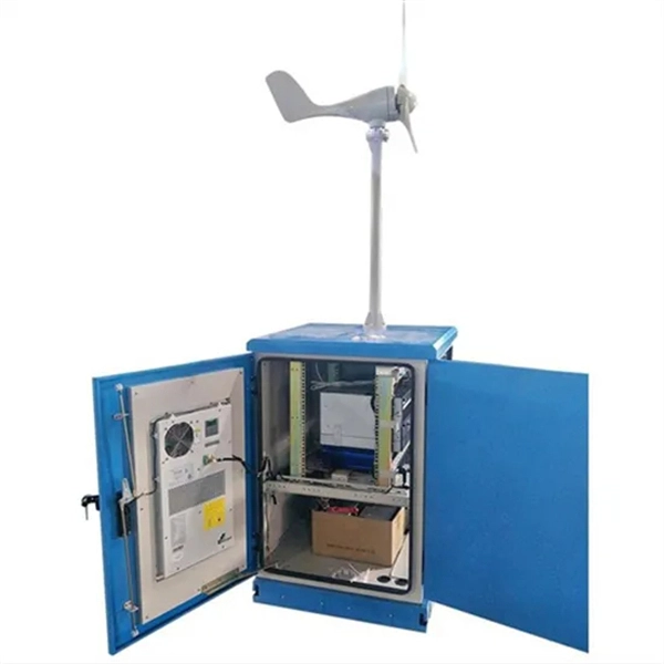
Photovoltaic systems can be simple to complex. There can be many components such as photovoltaic panels, collector or combiner boxes, battery systems, charge controllers, and inverters. There are
Complete Protection of Photovoltaic (PV) systems
Photovoltaic AC and DC sides protection According to the IEC 61643-32 regulation, the PV installations must be always protected by SPD''s both on the AC side and the DC side. The regulation makes a

Protection Relaying Practices in Solar PV Systems
For BESS systems, overvoltage, overcurrent, earth fault and undervoltage protection are essential to safeguard both the battery and the inverter. The protection relays for BESS systems
690 ARTICLE Solar Photovoltaic (PV) Systems
Article 690 applies to photovoltaic (PV) electrical energy systems, array circuit(s), inverter(s), and charge controller(s) for PV systems, which may be interactive with other electrical power sources (elec-tric
Relay Protection Coordination for Photovoltaic Power Plant
As can be seen in Fig. 9, the fault be isolated from the 35 kV feeding network by protection device P1 (it will trip after 0.01 s) and from the side of the PV power plant by protection P3 (circuit breaker I> will
An Introduction to Protective Relays for Solar-Plus
In this article, we''ll explain how protective relays work, review some of the most common relay functions for solar and energy storage systems, and
Standards for Relay Protection in Renewable Energy
By adhering to relay protection standards, such as the IEEE C37 series and the IEC 61850 series, renewable energy systems can ensure reliable and coordinated protection, minimizing
Installing and Maintaining Protective Relay Systems
Verify that the relay elements operated properly, that appropriate communication transmit and receive signals were present, and that proper timing between relay elements, signals, and breaker
The Relay Protection Coordination for Photovoltaic Power Plant
Fig. 9. Time-current curves of the protection devices for the case of three-phase short circuit at the location 2 As can be seen from the Fig. 9, the fault be isolated from the 35 kV feeding
An adaptive protection coordination scheme for microgrids with
This paper presents a protection coordination scheme in MGs with optimum penetration levels of PV resources without requiring communication platform between relays and central control
Optical Power Meters & Sources
High-precision power meters (Ge/InGaAs) and stabilized light sources for insertion loss and return loss testing.
OTDR & Fiber Characterization
Full-featured OTDR, fiber OTDR testers, and modular OTDR test modules for network deployment and troubleshooting.
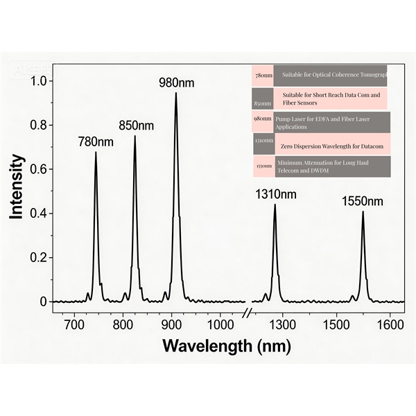
OSA & Eye Diagram Analyzer
High-resolution OSA for DWDM and eye diagram testers for signal integrity validation.
BERT & Endface Inspection
BERT up to 800G, fiber endface inspection probes, and extinction ratio meters for comprehensive testing.