
Cable Tray Clearance Standards | PDF | Manufactured
This document outlines clearance requirements for cable trays. It provides a table with clearance dimensions labeled a through k for typical and special clearance
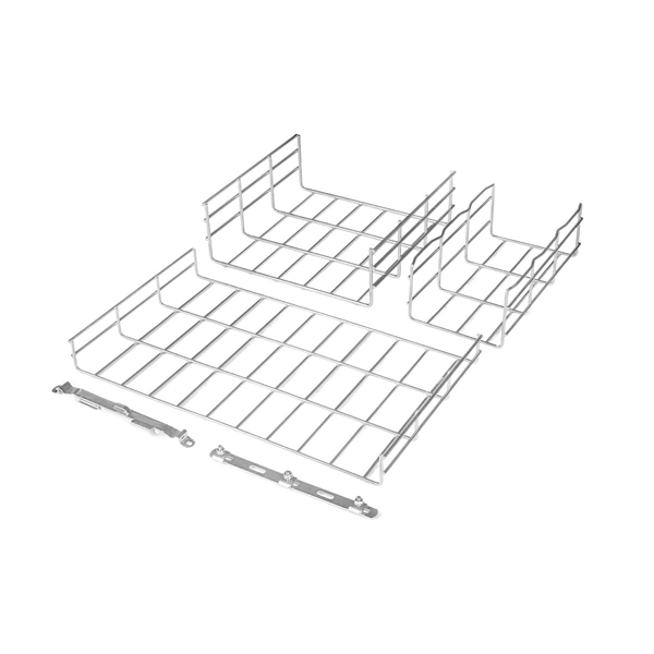
Cable Tray Technical Guide A practical guide to product selection
Cable tray length is selected based on the load to be supported, the distance between the supports (also referred to as the span), and handling and installation constraints.
Explaining NEC Article 392 on Cable Trays
For the installation of single conductor cables sized 1/0 AWG to 4/0 AWG in industrial establishments, the NEC specifies the maximum allowable rung spacing for the cable tray.
B-Line series Cable Tray Design Considerations
Cables may exit or enter through the top or the bottom of the tray. Ladder cable tray without covers provides for maximum air flow, dissipating heat produced in current carrying conductors. Dust
CEC Code Rule 12-2200 CT Clearances | PDF
Cable trays shall be installed as a complete system using fittings or other means to provide adequate cable support and bending radius before the conductors are installed.

CABLE TRAY SYSTEMS GUIDE
Commonly called the Load Class, this defines the load-carrying capability of the tray for a specific support span distance. The design and cost of the cable tray is greatly affected by this designation.
Cable tray install | Information by Electrical Professionals for
In general, vertical spacing for cable trays should be 30 cm (12 in), measured from the bottom of the upper tray to the top of the lower tray. A minimum clearance of 23 cm (9 in) should be
Cable Tray Dimensions and Specifications as per NEC
The entire amount of the cross-sectional areas for all of the single conductor cables that are going to be positioned in the cable tray needs to be equal to or less than the permissible cable
Cable Tray Spacing Standards for Installation and Safety
Top Clearance: The top of the cable tray should maintain a minimum distance of 0.3 meters from the ceiling or any other obstructions. Tray Width: The width of the cable tray should be
Cable Tray Installation Rules (NEC 392) – Electrical Trader
The 2026 NEC introduced an important update: cable trays must have at least 12 inches of clear vertical space above them to allow for installation and maintenance access. When
Cable Tray Support Spacing: Key Guidelines Explained
Explore the essential cable tray support spacing requirements for safe and efficient installations. Learn NEC guidelines for perforated, ladder, and wire mesh trays.
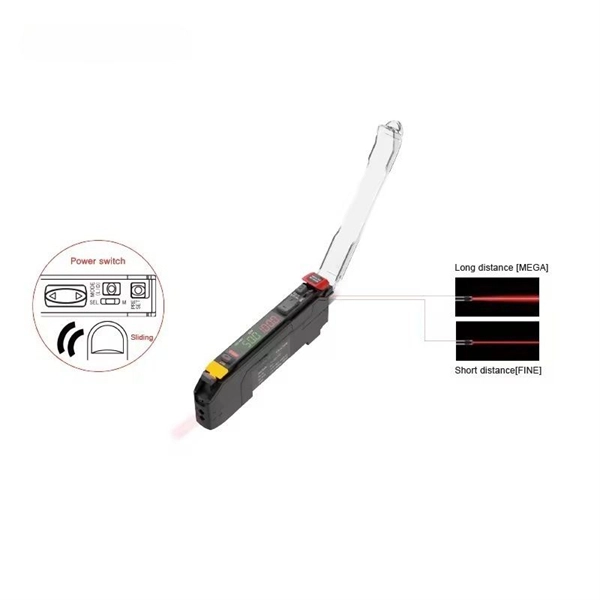
Optical Power Meters & Sources
High-precision power meters (Ge/InGaAs) and stabilized light sources for insertion loss and return loss testing.
OTDR & Fiber Characterization
Full-featured OTDR, fiber OTDR testers, and modular OTDR test modules for network deployment and troubleshooting.
OSA & Eye Diagram Analyzer
High-resolution OSA for DWDM and eye diagram testers for signal integrity validation.
BERT & Endface Inspection
BERT up to 800G, fiber endface inspection probes, and extinction ratio meters for comprehensive testing.