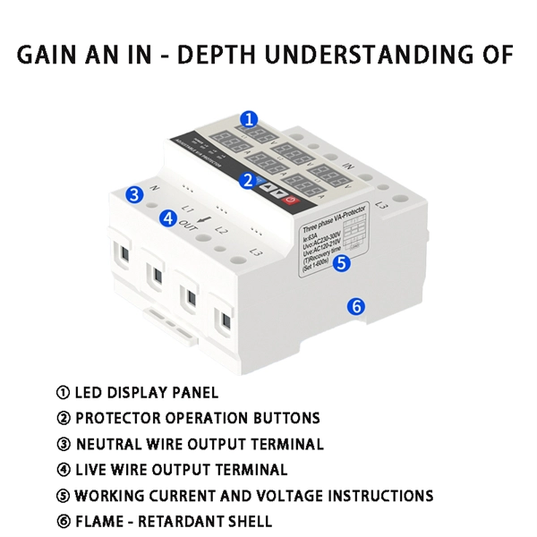
Cable Tray Conductor Sizing Guide
Fill is the amount of tray width or cross-sectional space occupied by cables, which matters because crowded trays trap heat and make maintenance harder. Step-by-Step Cable Tray Sizing
Cable Tray Installation Rules (NEC 392) – Electrical Trader
The 2026 NEC introduced an important update: cable trays must have at least 12 inches of clear vertical space above them to allow for installation and maintenance access.
Cable Tray Fill Rules (NEC 392)
Support spacing: NEC 392.18 requires cable trays to be supported at intervals consistent with the manufacturer''s installation instructions, but not more than the maximum span listed for the

Cable Tray Technical Guide A practical guide to product selection
As per the NEC, the maximum allowable rung spacing is 9 inches (230 mm) when cable tray carries sin-gle-conductor cables of 1/0 to 4/0 AWG (American Wire Gauge) (Appendix I).

Core Principles for Electrical and Instrumentation Cable Tray Layouts
Spacing Standards: Electrical (power) and instrumentation (signal/control) cable trays should maintain a minimum vertical and horizontal distance. Industry standards often recommend at least 300mm (12

Cable Tray SHIB NAL.pmd
A generic guideline developed by the Cable Tray Institute indicates that cable trays should not be filled in excess of 40-50% of the inside area of the tray or of the tray''s maximum weight based on the cable
Cable Tray Support Spacing: Key Guidelines Explained
Explore the essential cable tray support spacing requirements for safe and efficient installations. Learn NEC guidelines for perforated, ladder, and wire mesh trays.
NEC Article 392 Guide: Ensuring Compliance for Cable Tray Systems
Strong hangers or brackets should be used to ensure that cable trays do not fall or hang. According to the regulations under NEC 392.30, these supports have to be put at a consistent
Cable Tray Dimensions and Specifications as per NEC
The entire amount of the cross-sectional areas for all of the single conductor cables that are going to be positioned in the cable tray needs to be equal to or less than the permissible cable
A Guide to Installing and Supporting Electrical Cable Trays
Cable Tray Support Span: The distance between supports is a critical calculation. The cable tray support span must be determined based on the manufacturer''s load capacity chart and the total anticipated
Optical Power Meters & Sources
High-precision power meters (Ge/InGaAs) and stabilized light sources for insertion loss and return loss testing.
OTDR & Fiber Characterization
Full-featured OTDR, fiber OTDR testers, and modular OTDR test modules for network deployment and troubleshooting.
OSA & Eye Diagram Analyzer
High-resolution OSA for DWDM and eye diagram testers for signal integrity validation.
BERT & Endface Inspection
BERT up to 800G, fiber endface inspection probes, and extinction ratio meters for comprehensive testing.