Fiber U Basic Skills Lab Workbook-testing
Create a simulated cable plant with some fiber optic cables long enough to be seen by the OTDR, typically 10-100 meters or more. (It''s called “Cable Under Test” in the drawing above.)
Inspection and Cleaning Procedures for Fiber-Optic Connections
The procedures in this document describe basic inspection techniques and processes of cleaning for fiber optic cables, bulkheads, and adapters used in fiber optic connections.

Standard for Installing and Testing Fiber Optics
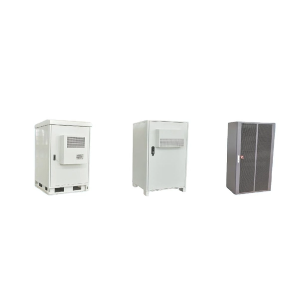
Although most fiber optic cables are not conductive, any metallic hardware used in fiber optic cabling systems (such as wall-mounted termination boxes, racks, and patch panels) must be grounded.
Fiber Optic System Testing Tutorial
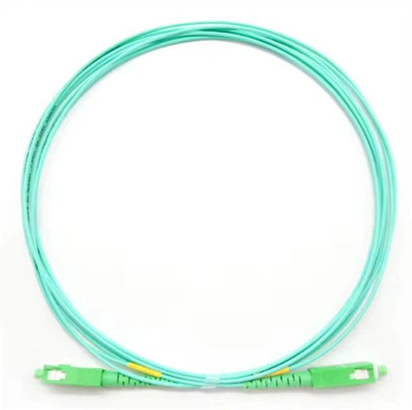
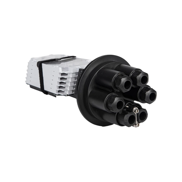
Patch cords or equipment jumpers are used to bridge the network electronic ports to the fiber optic link contained between patch panels (also known as “cross-connects”). Figure 1 below
Inspecting & Diagnosing Fiber Optic Connections
In pecting & Diagnosing Fi 1. Visual Inspection Scope must be carried out prior to all cable testing. Minor defects or sc atches are acceptable while major ones are not. The critical area is the core zone which
Fiber Optic Cable Inspection Checklist | PDF | Optical
This document provides a fiber optic cable inspection checklist. It includes sections for general information about the inspection such as date, location, cable type. It
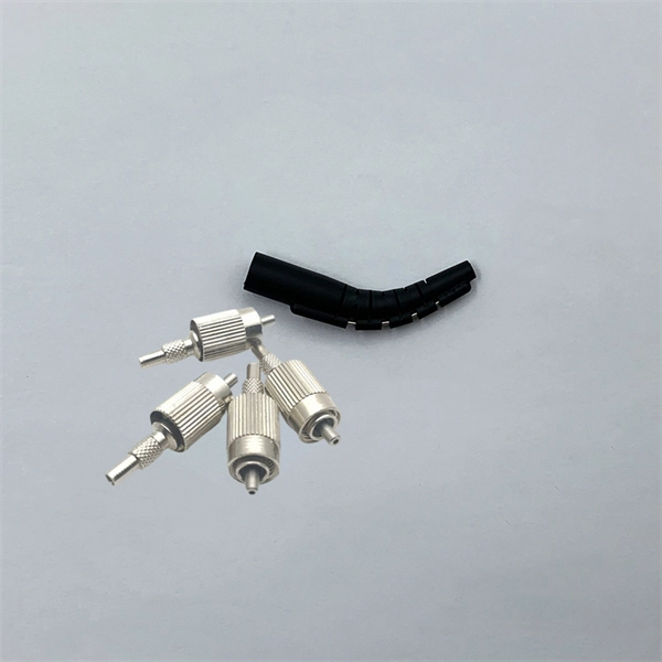
Ch 5-Fiber Optic Cable
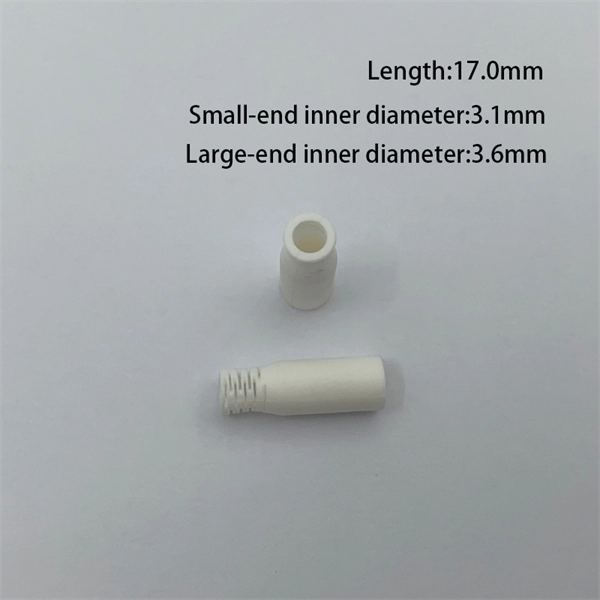
Fiber optic cable (FOC) is a cable assembly that utilizes optical fibers, which are transparent strands of glass only slightly thicker than a human hair, to transmit communications signals in the form of light.
Fiber Optic Cable Installation and Handling Instructions
The information contained in this manual should serve as a guide to proper handling, installing, testing, and for troubleshooting problems with fiber optic cables.
Fiber Optics inspection, cleaning and testing
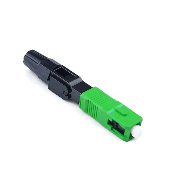
There are three main principles that needs to be taken in consideration for an efficient optical connection: a perfect core alignment, perfect physical contact and dirt-free connectors.
Visual Inspection and Cleaning of Multimode and Single Mode
All fiber connectivity in the cabling system shall be subject to inspection and cleaning according to the guidelines presented herein. For the purposes of this document, connectivity systems consist of the
Optical Power Meters & Sources
High-precision power meters (Ge/InGaAs) and stabilized light sources for insertion loss and return loss testing.
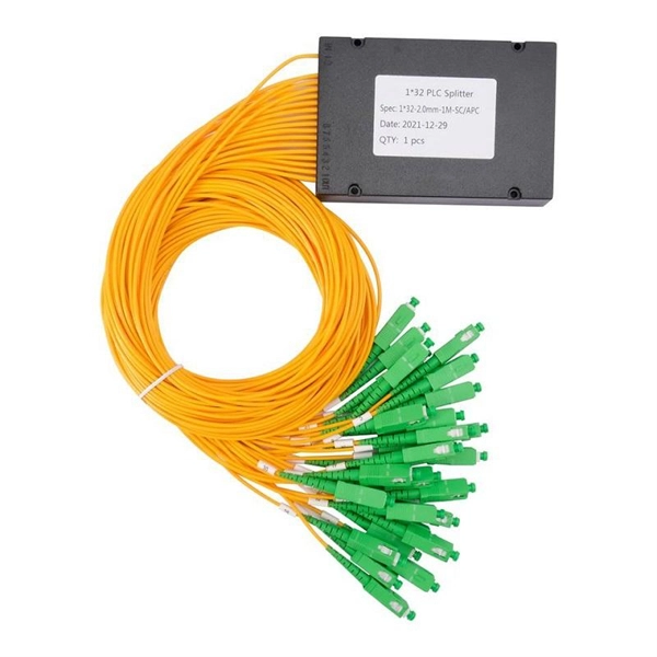
OTDR & Fiber Characterization
Full-featured OTDR, fiber OTDR testers, and modular OTDR test modules for network deployment and troubleshooting.
OSA & Eye Diagram Analyzer
High-resolution OSA for DWDM and eye diagram testers for signal integrity validation.
BERT & Endface Inspection
BERT up to 800G, fiber endface inspection probes, and extinction ratio meters for comprehensive testing.