Cable Tray SHIB NAL
A generic guideline developed by the Cable Tray Institute indicates that cable trays should not be filled in excess of 40-50% of the inside area of the tray or of the tray''s maximum weight based on the cable
Cable Tray Dimensions and Specifications as per NEC
Many electrical systems employ cable trays. They route cables safely & efficiently. NEC defines minimum cable tray size & electrical installation specifications. These guidelines protect

Cable Tray Technical Guide A practical guide to product selection
Cable tray length is selected based on the load to be supported, the distance between the supports (also referred to as the span), and handling and installation constraints.
Code Corner: 2023 NEC Article 690.31 (C) and (C) (2)
Historically, the NEC has allowed cable trays, but has lacked specific guidelines for sizing conductors and using smaller conductors like PV wire and
Cable tray install | Information by Electrical Professionals for
In general, vertical spacing for cable trays should be 30 cm (12 in), measured from the bottom of the upper tray to the top of the lower tray. A minimum clearance of 23 cm (9 in) should be
Cable Tray Installation Rules (NEC 392) – Electrical Trader
The 2026 NEC introduced an important update: cable trays must have at least 12 inches of clear vertical space above them to allow for installation and maintenance access.
Cable Tray Spacing Standards for Installation and Safety
This article provides an in-depth look at the cable tray spacing standards that should guide your next installation project. Let''s dive deeper into the specific cable tray spacing
A Guide to Installing and Supporting Electrical Cable Trays
A professional guide to installing electrical cable tray systems per NEC Article 392. Covers support, securing cables, and fill calculations.
Document DICOS
Cable trays of less than 12 feet (ft.) in length should be supported in a minimum of one location, and trays over 12 ft. in length should be supported at a minimum of two locations.
NEC Article 392 Guide: Ensuring Compliance for Cable Tray Systems
Master NEC Article 392 with our comprehensive guide. Learn essential cable tray requirements for installation, grounding, and fill capacity to ensure full electrical compliance.
CEC Code Rule 12-2200 CT Clearances | PDF
Cable trays shall be installed as a complete system using fittings or other means to provide adequate cable support and bending radius before the conductors are installed.
Optical Power Meters & Sources
High-precision power meters (Ge/InGaAs) and stabilized light sources for insertion loss and return loss testing.
OTDR & Fiber Characterization
Full-featured OTDR, fiber OTDR testers, and modular OTDR test modules for network deployment and troubleshooting.
OSA & Eye Diagram Analyzer
High-resolution OSA for DWDM and eye diagram testers for signal integrity validation.
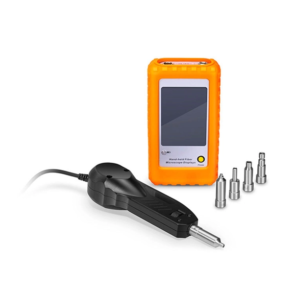
BERT & Endface Inspection
BERT up to 800G, fiber endface inspection probes, and extinction ratio meters for comprehensive testing.