S/PDIF Coaxial and Optical Splitter
This circuit was designed to split a single S/PDIF coaxial or optical digital audio signal to multiple outputs. It functions as either a 3-way splitter or format converter depending on jumper settings.

Tunable optical power splitter based on directional coupler structure
Traditional optical power splitters (OPSs) have fixed power split ratios, and although some can be tuned with an electro-optic polymer, continuous energy supply increases power consumption.
POWER SPLITTER ARCHITECTURES AND APPLICA
mance comparison along with their applications. Some of the applications are illustrated at the end of the paper, and re ommendation for further study is also outlined. This review serves as a comparative
4 Ways Active Power Splitter, 2.4
Mini-Circuits is a global leader in the design and manufacturing of RF, IF, and microwave components from DC to 86GHz.
Reeve_VLF-LF-Splitter
An RF signal splitter (also called divider or power divider) takes an input from an antenna or other signal source and directs it to two or more output paths for connection to test equipment or receivers.
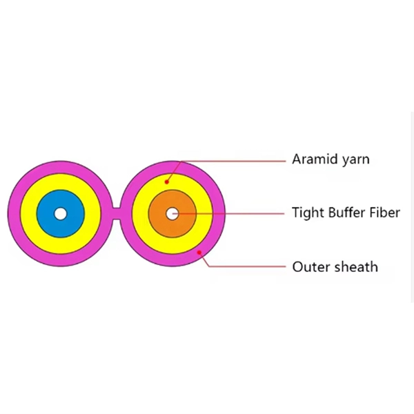
Application of Optical Splitter in FTTH Network
Optical splitter is one of the most important passive components in optical fiber links and plays an important role in FTTH passive optical networks.

(PDF) Power Splitter Architectures and Applications
The wideband active power splitter block diagram is shown in Figure 2. The proposed circuit uses common drain FET configuration because of its high input and low output impedance
ADA4304-2 (Rev. A)
The ADA4304-2 consists of a low noise buffer amplifier followed by a resistive power divider. This arrangement provides 2.8 dB of gain relative to the RF signal present at the input of the device.
Power Supply Splitter circuit using op-amp
So, you should build a power supply splitter circuit like this. Often the many op-amps have this problem. They need a split supply. The output terminal has positive, negative, and ground.
Active differential output power splitter schematic.
This letter deals with the design of an active balun exhibiting a single-ended input and balanced outputs.

RF Power splitter design
Secondly, i wanna inform you that i need a splitter ckt after the RF Power Amplifier''s output & before antennas. The main purpose of this splitter ckt is to split one signal into three parallel
Optical Power Meters & Sources
High-precision power meters (Ge/InGaAs) and stabilized light sources for insertion loss and return loss testing.
OTDR & Fiber Characterization
Full-featured OTDR, fiber OTDR testers, and modular OTDR test modules for network deployment and troubleshooting.
OSA & Eye Diagram Analyzer
High-resolution OSA for DWDM and eye diagram testers for signal integrity validation.
BERT & Endface Inspection
BERT up to 800G, fiber endface inspection probes, and extinction ratio meters for comprehensive testing.