Fiber Design Documents / Schematics : r/FiberOptics
Lumen doesn''t have as large of a footprint so theirs is a map of the ring and boxes for splice locations and fibers they want you to use, even though the fibers can change at anytime for
Understanding Network Diagrams and Splice Diagrams
Fiber optic network diagrams represent the architecture and connectivity of fiber optic systems, and their design philosophy integrates technical, functional, and conceptual aspects. The
Schematic diagram of cable double ring network connection (ring network
Aiming at the problems of low power supply reliability, poor transfer capacity between stations, and low line utilization in the current distribution network, this paper proposes a diamond-shaped...

Fiber Optic Ring Network Design Explained: Topologies, Diagrams
Learn how to design a fiber optic ring network with practical diagrams, topologies, and switch setup tips. Explore ring network switch options for industrial applications.
Technical Drawings
Technical Drawings Technical Resources BIM, CAD, Visio and PDF Files for Copper & Fiber Optic Cabling, Racks & Cabinets
Continuum Splice Matrix Examples
A simple splice diagram with 132 fibers and 66 splices. The first drawing, with 2,160 fibers and 562 splices, uses a more efficient format and is easier to read.
Schematic diagram of cable double ring network
Aiming at the problems of low power supply reliability, poor transfer capacity between stations, and low line utilization in the current distribution network, this paper
FIBER OPTICS
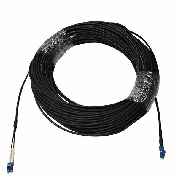
At the splice points, the fiber cable is wrapped with fire retardant tape. 75 feet of extra cable is coiled for each end. The coils are stored in a fire resistant cloth bag (FIBFB001).
How to Splice Fiber Optic Cable – Step-by-Step Fusion Splicing Guide
Learn how to splice fiber optic cable using fusion splicing with this complete step-by-step guide. Includes tools, best practices, loss standards (ITU-T G.652), cost analysis, and FAQs for
TR-3552: Optical network installation guide
Splicing methods for optical fibers fall into two main categories: (i) fusion splicing, and (ii) mechanical splicing. Fusion splicing consists of aligning and then using an electric arc to fuse together two

Splice Drawing for Fiber Optic Cables | PDF | Leisure
Key details provided for each connection include cable IDs, core numbers assigned, and expected maximum signal loss between 1310nm and 1550nm wavelengths.
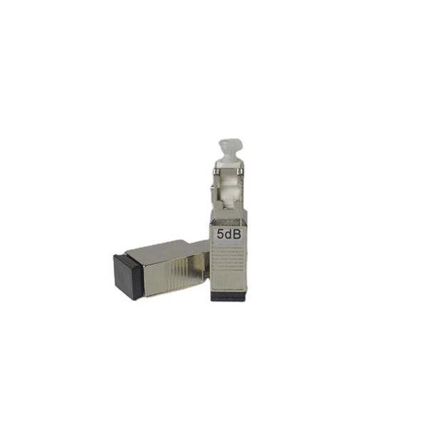
Optical Power Meters & Sources
High-precision power meters (Ge/InGaAs) and stabilized light sources for insertion loss and return loss testing.
OTDR & Fiber Characterization
Full-featured OTDR, fiber OTDR testers, and modular OTDR test modules for network deployment and troubleshooting.
OSA & Eye Diagram Analyzer
High-resolution OSA for DWDM and eye diagram testers for signal integrity validation.
BERT & Endface Inspection
BERT up to 800G, fiber endface inspection probes, and extinction ratio meters for comprehensive testing.