
N-Way Power Divider Calculator
This calculator calculates the total power lost from the input of the power divider to the output of each port based on its configuration. It also accounts for other losses in the system.
How to Calculate Optical Splitter Loss
This means that if you measured the Insertion Loss for all output ports on that splitter, the difference between the highest loss reading and the lowest loss reading would be no more than 1.0 dB.
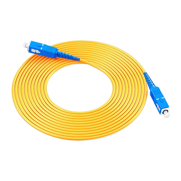
Ubiquiti UFiber Splitter GPON Fiber Splitter 16 SC/APC Ports G.657A1
High-Quality Fiber: Uses G.657A1 fiber for reliable signal transmission over long distances. Low Insertion Loss: Ensures minimal signal degradation with loss values of 7.4 dB (4-port), 10.5 dB (8
N-Way Power Divider Calculator
Pasternack''s N-Way Power Divider Calculator allows you to calculate the total path loss (in dB) you can expect based on the number of output ports on the RF power splitter device (up to 16 ports).

RF Splitter Calculator
An RF Splitter (also known as a power divider) is used to split the input signal into 2 or more equally powered signals. This tool calculates the total loss in dB of the signal on any of the output ports.
1x8 and 1x16 splitters : r/FiberOptics
Based on materials I''ve found on the internet, 26.5 dB should be maximum (with 5% tolerance). Also if this wont work on actual application, what are the other design options you would suggest?
Signal Split Decision: Understanding the Impact of Splitters on Your
The amount of signal loss depends on the type of splitter used and the number of splits. A typical splitter can introduce a signal loss of 3-6 decibels (dB) per split. The signal loss can be a
Power Divider Calculator
Calculate the path loss in dB for a power divider based on the number of output ports. Useful for RF and microwave circuit design.
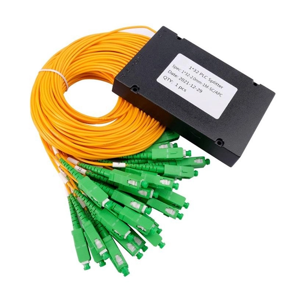
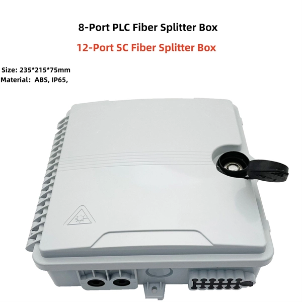
PLC Splitter and download the loss chart of PLC splitter
A splitter with 1×2 certain ratio configuration means that it has one input and two outputs. There are 1×4 plc splitter, 1×8 plc splitter, 1×16 plc splitter, 1×32 splitter, and so on. Here is a table of
Understanding Signal Loss in PLC Splitters: A Comprehensive Analysis
Excess loss typically ranges from 0.5 to 1.5 dB depending on the splitter quality and manufacturing process. This loss adds to the splitting loss and affects all ports uniformly in well
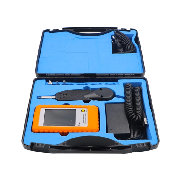
Optical Power Meters & Sources
High-precision power meters (Ge/InGaAs) and stabilized light sources for insertion loss and return loss testing.
OTDR & Fiber Characterization
Full-featured OTDR, fiber OTDR testers, and modular OTDR test modules for network deployment and troubleshooting.
OSA & Eye Diagram Analyzer
High-resolution OSA for DWDM and eye diagram testers for signal integrity validation.
BERT & Endface Inspection
BERT up to 800G, fiber endface inspection probes, and extinction ratio meters for comprehensive testing.