DIY Wiring a Consumer Unit and Installation
A Sub Circuit can be an electric cable distributing power to few lights, or a socket outlet/s through a MCB device or a Fuse in the Distribution Board. Here we are considering a Distribution Board with MCBs
How to Determine Your Electrical Service Amps
These individual, or branch, circuit breakers are numbered, and they control individual branch circuits running through your home. The amperage of these individual breakers will be

How to Size Feeder Conductors with Overcurrent Protection
Feeder conductors are used to carry electrical current from the main service equipment to subpanels, distribution panels, or branch circuits. They must be sized based on the calculated load demand and
Panel Schedule Calculator | Load Distribution & Balancing
Professional electrical panel schedule tool for creating detailed load distributions, calculating circuit loads, balancing phases, and ensuring NEC compliance for electrical distribution panels.
How Electricity Is Distributed to Branch Circuits
Once the current passes through the protective device, it enters the final stage of distribution: the branch circuit. A branch circuit is defined as the wiring path that extends from the final overcurrent
How to Determine Your Electrical Service Amps
These individual, or branch, circuit breakers are numbered, and
How to Calculate the Size and Number of Circuits for a Distribution
That''s what happens when you overload circuits. But with some simple math and planning (don''t worry, we''ll walk through it!), you can design a system that works smoothly even when you''re
Single Phase Distribution Box (DB) Wiring Diagram and Connection
The operating current rating of the RCCB should be the same as the Main MCB. Generally, 30mA sensing current-rated RCCBs are used for single-phase domestic installations.
Single Phase Distribution Board Wiring Guide
The document outlines the wiring of a single-phase distribution board (DB) with specific accessories and preparation for various circuits. It details the method of wiring sub circuits, installation of the DB, and
Calculate Size of Main ELCB & Branch MCB of Distribution Box
Design Distribution Box of one House and Calculation of Size of Main ELCB and branch Circuit MCB as following Load Detail. Power Supply is 430V (P-P), 230 (P-N), 50Hz. Consider
Power Distribution Systems
Single-Line or (One-Line) Diagram as: “A diagram which shows, by means of single lines and graphic symbols, the course of an electric circuit or system of circuits and the component devices or parts
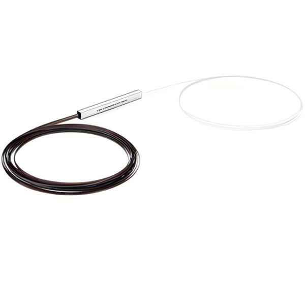
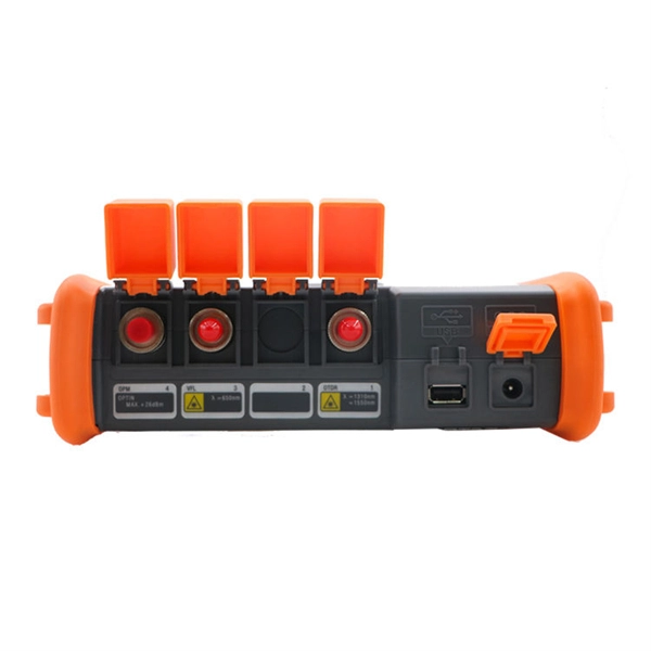
Optical Power Meters & Sources
High-precision power meters (Ge/InGaAs) and stabilized light sources for insertion loss and return loss testing.
OTDR & Fiber Characterization
Full-featured OTDR, fiber OTDR testers, and modular OTDR test modules for network deployment and troubleshooting.
OSA & Eye Diagram Analyzer
High-resolution OSA for DWDM and eye diagram testers for signal integrity validation.
BERT & Endface Inspection
BERT up to 800G, fiber endface inspection probes, and extinction ratio meters for comprehensive testing.