Calculating Fiber Optic Loss Budgets
Attenuation and bandwidth/dispersion are the key parameters for the cable plant loss budget analysis. FOA has a online Loss Budget Calculator web page that will
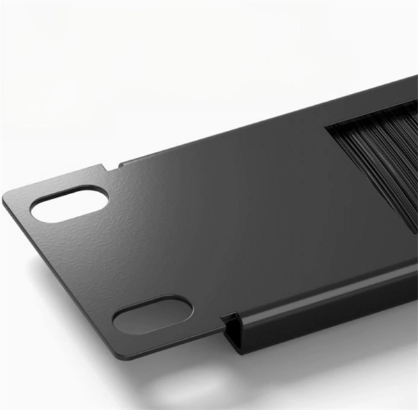
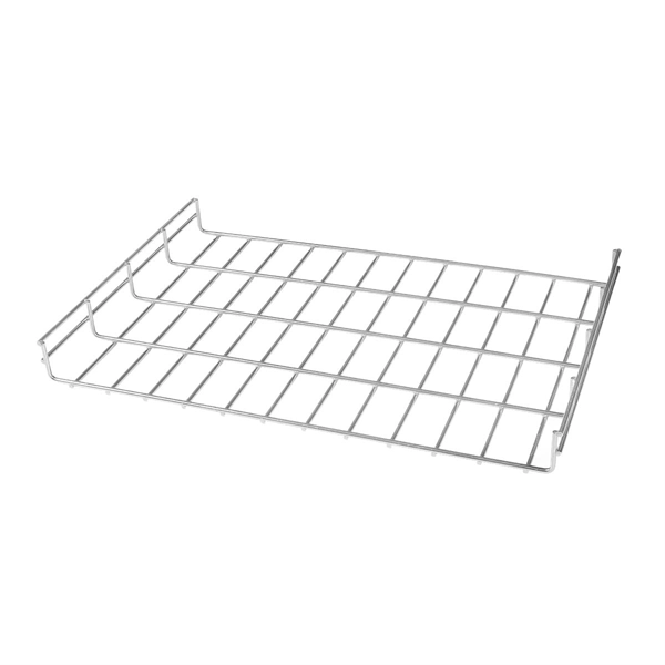
GUIDE CABLE TRAYS TECHNICAL
NEMA VE 1-2017 Specifies requirements for metal cable trays and associated fittings designed for use in accordance with the rules of Canadian Electrical Code, Part I and the National Electrical Code®
TECHNICAL AND SIZING DATA
By loading this tray more heavily, the designer must be careful not to exceed the total cable capacity as outlined in the Canadian Electrical Code (See following section on ladder tray sizing).

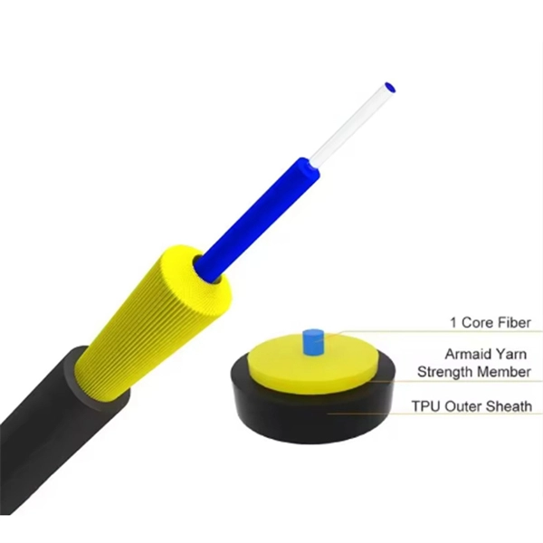
Optical Fiber Loss and Attenuation | MEETOPTICS Academy
Fiber loss, also called fiber optic attenuation or attenuation loss, refers to the loss of signal between input and output. Losses can be introduced by various means such as intrinsic material absorption,
Fiber Optic Testing Standards
An Optical Power Meter and Laser Light Source will be used to measure power loss on each completed ring or distribution span to verify continuity between fibers (no fibers incorrectly spliced together).
FOA Standard For Installing Fiber Optic Cable Plants
Optical Loss Test Set (OLTS) Tester comprised of fiber optic power meter and test source used to test the loss of components or cable plants. It may be two instruments or a combination of the two in one
Cable Trays and Optical Cables
The purpose of this AE Note is to outline the use of fiber optic cables in “tray rated” environments. The question arises as to what listing is required for an optical fiber cable installed in a cable tray.
Handbook Optical fibres, cables and systems
The optical fibres are specified in ITU-T with reference to the geometrical, optical, transmission and mechanical attributes listed in Table 1-1. However, as shown in the same table, for some attributes
Fiber Optic Cabling Loss Limits Explained – Trend Networks
Learn about fiber optic cabling loss limits & how to calculate them. Gain insights from experts on acceptable loss for cabling projects & explore the standards.
Attenuation In Optical Fiber, How to Calculate Fiber Loss?
In fiber optic cable installation, accurate measurement and calculation of attenuation in optical fiber is a very important step to verify network integrity and ensure network performance.
Technical Specification for Cable tray installation and cable laying
- Handled the optical cable with standard procedure and necessary care as the cable should not be damage during cutting, inserting in conduit and laying the same in the cable tray.
Guidelines On What Loss To Expect When Testing Fiber Optic Cables
To be able to judge whether a fiber optic cable plant is good, one does a insertion loss test with a light source and power meter and compares that to an estimate of what is a reasonable loss for that cable
IEEE Guide for the Design and Installation of Cable Systems in
Abstract:The design, installation, and protection of wire and cable systems in substations are covered in this guide, with the objective of minimizing cable failures and their consequences.
Enduro_Specification_Ladder Cable Tray_04-30-21
For International Standards, the manufacturer shall declare the tray system Safe Working Load (SWL) per the International Electrotechnical Commission (IEC) 61537 and publish in the form of a table or
Cable Tray Technical Guide A practical guide to product selection
In designing supports for a cable tray system, consideration should be given to the loads associated with future cable additions and any additional loading that may be applied to the cable tray system (e.g.,
Optical fiber tables and chromatic dispersion specs
In this table, 802.3 has analyzed available information on connector loss, optical return loss and PMD in order to define optical channel characteristics for those parameters that are specific to these PMDs.
"Typical Derating Calculation for Tray."
The depth of cables luuted in trays that contain well below 50% tray fill is calculated per ICEA Publication P-54-440 Section 2.2 " Calculated Depth of Cables in Trays" as follows:
Calculators and Tools
Quickly and accurately calculate the link or channel loss in an innovative manner and find the supported applications for the configuration. This version also contains the Propel ULL products.
Optical Power Meters & Sources
High-precision power meters (Ge/InGaAs) and stabilized light sources for insertion loss and return loss testing.
OTDR & Fiber Characterization
Full-featured OTDR, fiber OTDR testers, and modular OTDR test modules for network deployment and troubleshooting.
OSA & Eye Diagram Analyzer
High-resolution OSA for DWDM and eye diagram testers for signal integrity validation.
BERT & Endface Inspection
BERT up to 800G, fiber endface inspection probes, and extinction ratio meters for comprehensive testing.