Cable Tray Size and Weight Chart | PDF | Wire
It lists the cable types, sizes, and quantities for each area. It then calculates the total cable outside diameter, weight per meter, and total weight for each area. Finally,

Firestopping Requirements for Cable Trays and Wall/Slab Penetrations
Cable trays and busways at floor level or at slab penetrations shall have a waterstop no less than 50 mm in height. At slab penetrations, provide 20–30 mm of firestopping and install a fire
Fire resistance requirements in context of cable tray capacity
Abstract: This article explores the fire resistance requirements in relation to cable tray capacity calculations, with a focus on theoretical frameworks and mathematical formulations.
Cable Tray SHIB NAL
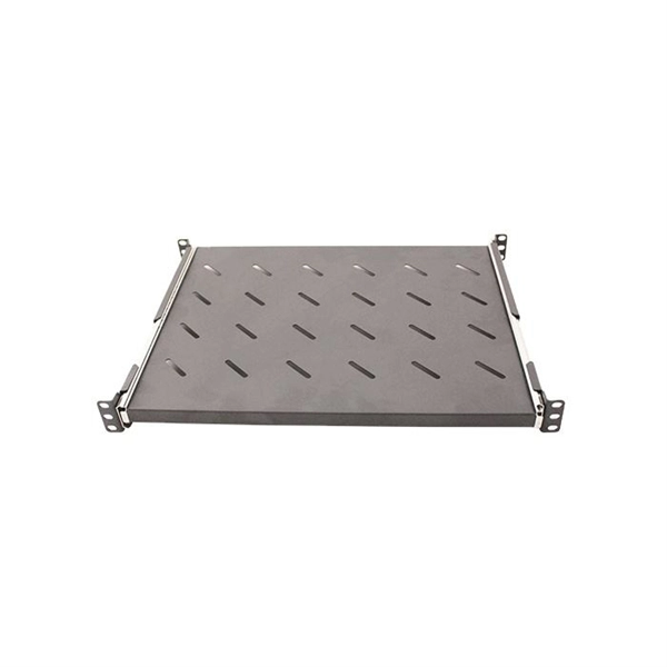
All cable trays and their associated supports are rated for a specific maximum weight, based partly on the allowable fill area and the spacing of the cable tray supports.
Technical Guidelines for Cable Tray Installation and Fireproofing
Select the tray width and thickness according to the number and weight of cables. Ensure mechanical strength is sufficient to prevent deformation or failure under full load.
Cable Ladder Cable Tray Weight Calculation Guide
In this guide, we''ll walk you through the step-by-step process for calculating cable tray weight, while providing examples for both channel trays and ladder trays.
GUIDE CABLE TRAYS TECHNICAL
When fitting cable trays and their accessories, the products are cut on site to create changes of direction, adjust sections, etc. Damage can also occur during handling; as a result, both the
Suppression of cable tray fire in utility tunnel power compartments
Utility tunnel cable systems face critical fire safety challenges due to dense cable arrangements and complex flame spread dynamics. This study investigates the suppression

Firestopping Requirements for Cable Trays and
Cable trays and busways at floor level or at slab penetrations shall have a waterstop no less than 50 mm in height. At slab penetrations, provide
Technical Guidelines for Cable Tray Installation and
Select the tray width and thickness according to the number and weight of cables. Ensure mechanical strength is sufficient to prevent deformation or failure under
LEGRAND CABLE TRAYS TECHNICAL GUIDE
When fitting cable trays and their accessories, the products are cut on site to create changes of direction, adjust sections, etc. Damage can also occur during handling; as a result, both the

Vogtle Electric Generating Plant (VEGP) Units 3 and 4 Updated
Dead load includes the weight of the cable trays, their supports and the cables inside the trays and any permanently attached items. Temporary items used during construction or maintenance are removed
Westinghouse AP1000 Design Control Document Rev. 19
Section properties and weights of the trays are obtained from manufacturer''s data. The maximum damping ratio is 10 percent unless the configuration is demonstrated to be similar to that of the tests

IEC Standard for Cable Tray: Complete Technical Guide
The cable tray must withstand the load of cables, environmental factors, and external pressure. IEC 61537 specifies load testing methods to validate tray strength.
Optical Power Meters & Sources
High-precision power meters (Ge/InGaAs) and stabilized light sources for insertion loss and return loss testing.
OTDR & Fiber Characterization
Full-featured OTDR, fiber OTDR testers, and modular OTDR test modules for network deployment and troubleshooting.
OSA & Eye Diagram Analyzer
High-resolution OSA for DWDM and eye diagram testers for signal integrity validation.
BERT & Endface Inspection
BERT up to 800G, fiber endface inspection probes, and extinction ratio meters for comprehensive testing.