How to Ground an Electrical Panel Safely and Effectively
Follow a clear step-by-step process: install the ground rod deeply, connect the grounding wire securely, attach it to the panel''s ground bus bar, and test the system with proper equipment.
How to Ground an Electrical Panel: A Complete Guide
A #6 AWG copper grounding wire is typically used to connect the panel to the rod. It''s thick enough to handle faults safely without overheating. A sturdy grounding clamp will secure the
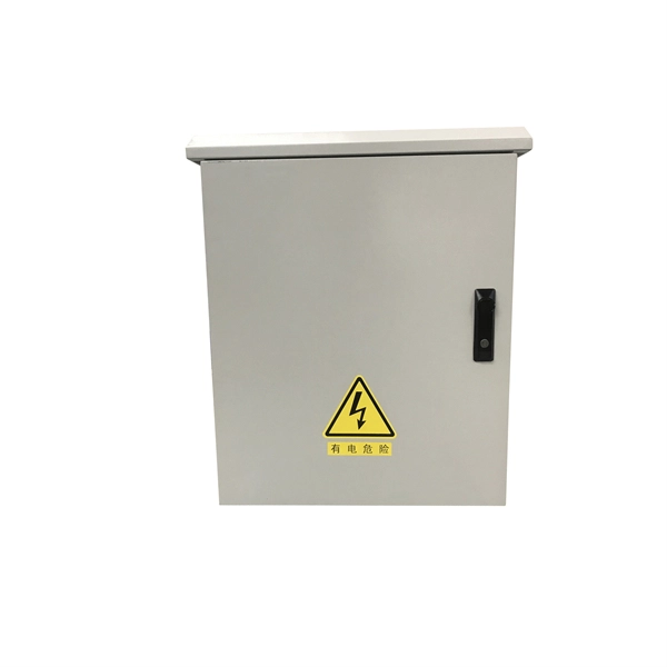
Correct Connection Method Of Grounding Wire Of Distribution Box
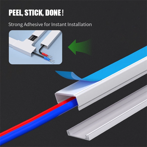
When connecting, it is necessary to strip the wire for a distance, then connect it to the terminal, and tighten the screw with a screwdriver to ensure a firm connection.
Grounding and Bonding an Electrical Panel
This video will show you how to drive grounding rods, run grounding wire to them and into the electrical panel, and how to bond the panel.
How To Ground An Electrical Panel: 8 Steps With Video
First, attach one cable end to the ground rod or neutral bar inside the electrical panel using a size 6 copper grounding wire. To reduce unnecessary bending of the ground path, carefully
Electrical Box Ground Wire Connectors & Connections
How to make proper & safe electrical ground wiring connections in the box: This article describes options for connecting a metal electrical box to the grounding conductor & connecting the

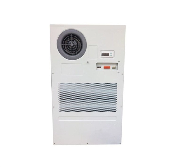
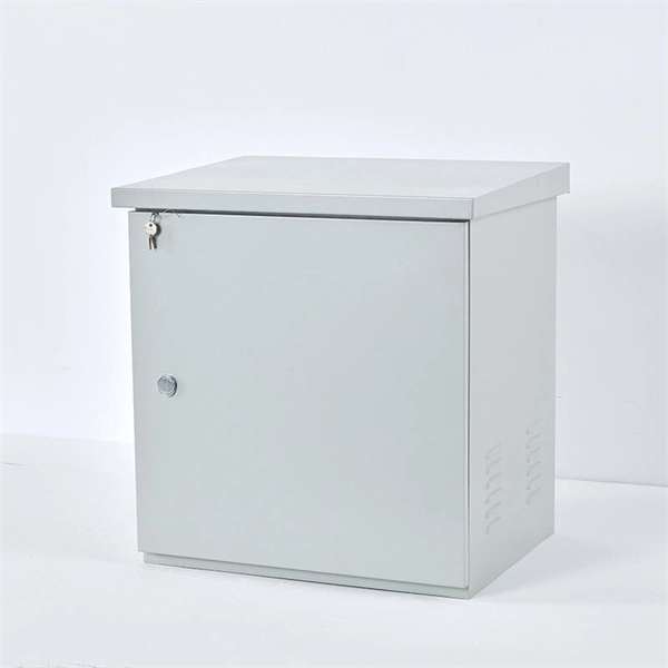
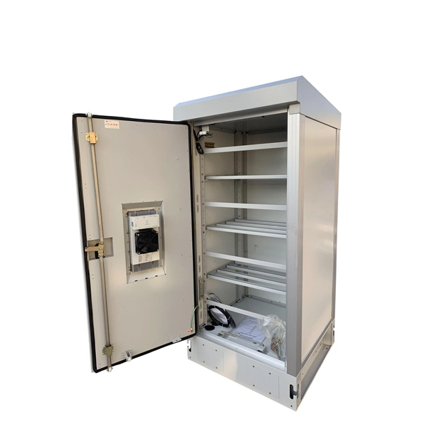
DISTRIBUTION BOX
Attach a ground wire from one of the threaded studs (A) at the bottom of the housing, to the mounting plate (B). Attach a second grounding wire from the mounting plate (B), to the factory
How to Run a Ground Wire to an Electrical Panel in 10
This article will tell you how to run a ground wire to an electrical panel & the importance of doing this task.
How do you ground a plastic electrical box
Install a ground wire: If your box doesn''t already have a ground wire, you need to install one first. One end of the ground wire should be connected to a metal part of the box and...
Correct Connection Method Of Grounding Wire Of
When connecting, it is necessary to strip the wire for a distance, then connect it to the terminal, and tighten the screw with a screwdriver to ensure a
How To Make Proper Grounding and Bonding Connections
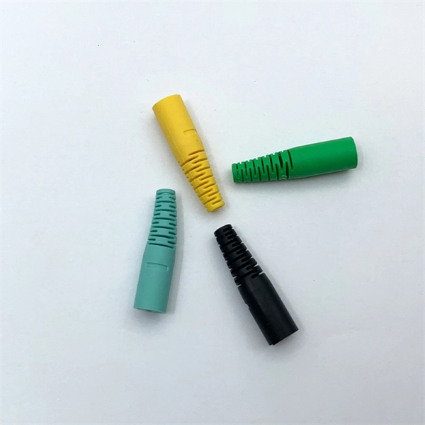
Listed pressure connectors are often used for bonding connections. Typical connectors are twist-on type connectors and tool-crimped connectors. At left is a green twist-on connector with a
Optical Power Meters & Sources
High-precision power meters (Ge/InGaAs) and stabilized light sources for insertion loss and return loss testing.
OTDR & Fiber Characterization
Full-featured OTDR, fiber OTDR testers, and modular OTDR test modules for network deployment and troubleshooting.
OSA & Eye Diagram Analyzer
High-resolution OSA for DWDM and eye diagram testers for signal integrity validation.
BERT & Endface Inspection
BERT up to 800G, fiber endface inspection probes, and extinction ratio meters for comprehensive testing.