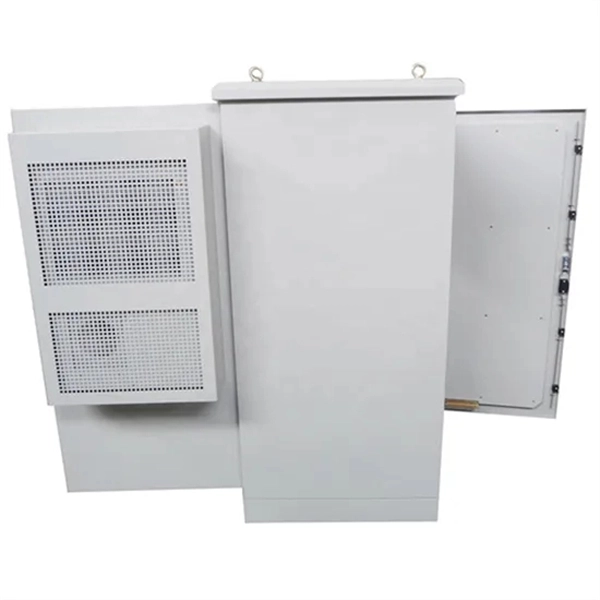
How to Build a DIY Temporary Power Distribution Box
Securely manage job site power. Build a compliant temporary distribution box, detailing component sizing, critical grounding, and wiring integrity.
Managing Electrical Safety for Temporary Power on Job
Improve temporary power safety with our expert guide. Learn about NEC Article 590, GFCI protection, grounding, and OSHA standards for qualified electricians.
Wiring diagram for temporary power poles: a comprehensive guide
In summary, connecting the power source to a temporary power pole involves the installation of a weatherproof electrical panel, the use of a suitable power cable, and the proper routing and

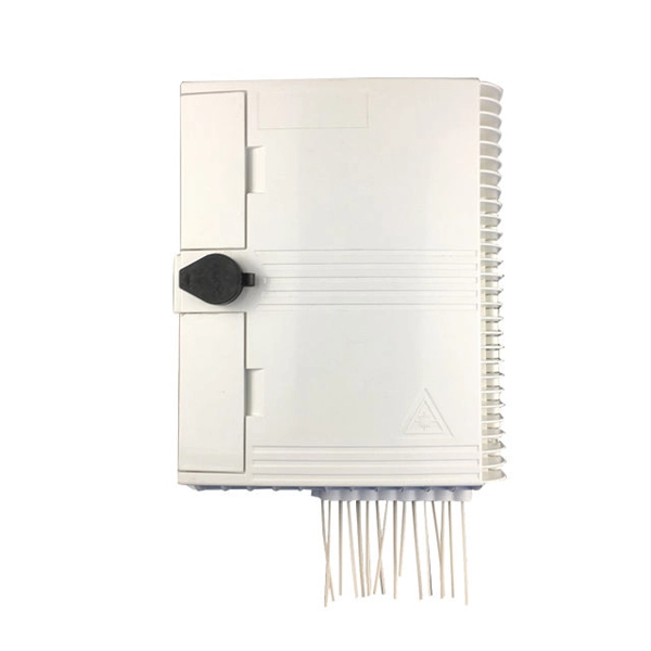
50-AMP 125/250V TEMPORARY POWER DISTRIBUTION BOXES
A: No, the power system that a 50-Amp 125/250V 3P 4W Temporary power Boxes requires is 3-Poles, Hot 1, Hot 2, Neutral, plus a Ground. The unit will not function correctly if adapted to a system that
Temporary Grounding and Bonding Techniques
Effective temporary grounding techniques must utilize a combination of grounding and bonding; grounding to clear accidental re-energization and minimize potential; bonding to ensure workers are
Electric Power Generation, Transmission, and
Installing grounds must be done in the proper sequence using a live-line tool. To install a ground, the point to be grounded on the equipment must first be tested to
Electrical Code rules for portable and temporary electrical power
All grounding conductors in an enclosure must terminate in a common grounding bus or lugs. The equipment grounding bar or lug(s) must be secured to the electrical enclosure with screws or bolts
Temporary electrical wiring for construction sites
All 120-volt, single-phase, 15- and 20-ampere recepta-cles shall be of the grounding type and their contacts shall be grounded by connection to the equipment grounding conductor of the circuit
Temporary Power Pole Diagram and Installation Guide
Install grounding equipment to protect the structure from surges or faults in the system. Verify proper spacing between components to ensure efficient distribution and prevent overheating.
Electric Power Generation, Transmission, and Distribution eTool
Installing grounds must be done in the proper sequence using a live-line tool. To install a ground, the point to be grounded on the equipment must first be tested to be sure it is not energized.
Grounding & Bonding-Temporary Power Generation and
This paper using simple terms and examples will discuss the grounding and bonding system as it relates to both permanent and temporary electrical system installations, specific
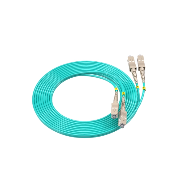
Optical Power Meters & Sources
High-precision power meters (Ge/InGaAs) and stabilized light sources for insertion loss and return loss testing.
OTDR & Fiber Characterization
Full-featured OTDR, fiber OTDR testers, and modular OTDR test modules for network deployment and troubleshooting.
OSA & Eye Diagram Analyzer
High-resolution OSA for DWDM and eye diagram testers for signal integrity validation.
BERT & Endface Inspection
BERT up to 800G, fiber endface inspection probes, and extinction ratio meters for comprehensive testing.