Substations Volume X Grounding
Without a properly designed grounding system, large potential differences can exist between different points within the substation itself. Under normal circumstances, it is the current flow through the
ARTICLE 250 Grounding and Bonding
The current path shown between the supply source ground-ing electrode and the grounding electrode at the service main shows that some current will flow through the earth but the earth is not part of the
Substation Grounding
Do not extend a substation fence or connect to a substation fence and extend outside of the ground grid. This extends the need for touch potential grounding. If you need to attach a fence to the substation

6B.6—Substation Grounding
Substation grounding design shall provide a continuous grounding system consisting of a buried main ground grid with ground rods. All equipment, structures, fencing, gates, and buildings shall be
Best practice in power substation grounding
The proper grounding of a substation is essential and very important for the following two reasons. First, it provides a means of dissipating electric current into the earth without exceeding the
GROUNDING OF UTILITY AND INDUSTRIAL DISTRIBUTION
A brief introduction to the design of substation grounding has been included. Detailed information on ground electrodes and measurement of ground resistance is also available.

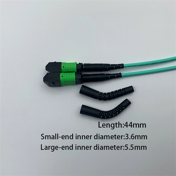
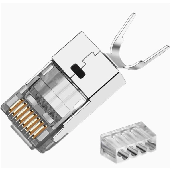
Indoor Fiber Optic Bonding & Grounding
Bonding and grounding is required for the safe and effective dissipation of unwanted electrical current that may arise in a telecommunications system. Bonding and grounding promotes
GROUND GRID SPECIFICATIONS
Each Power Circuit Breaker or Power Transformer having a bushing Voltage Transformer on the tank shall have the Voltage Transformer provided with a separate ground lead, independent of the
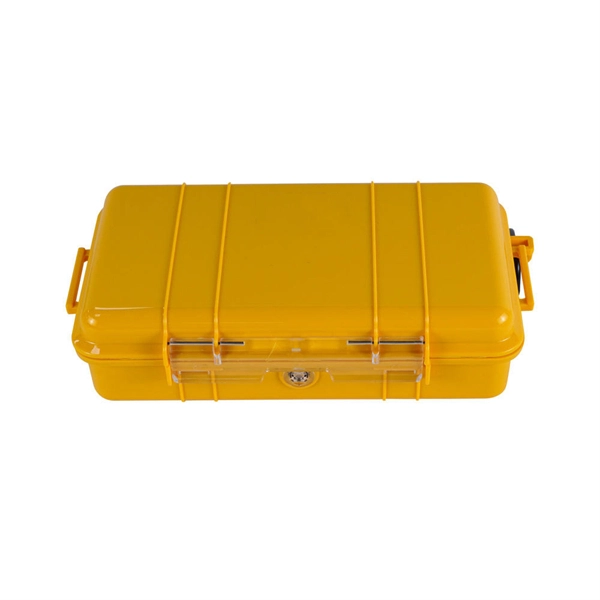
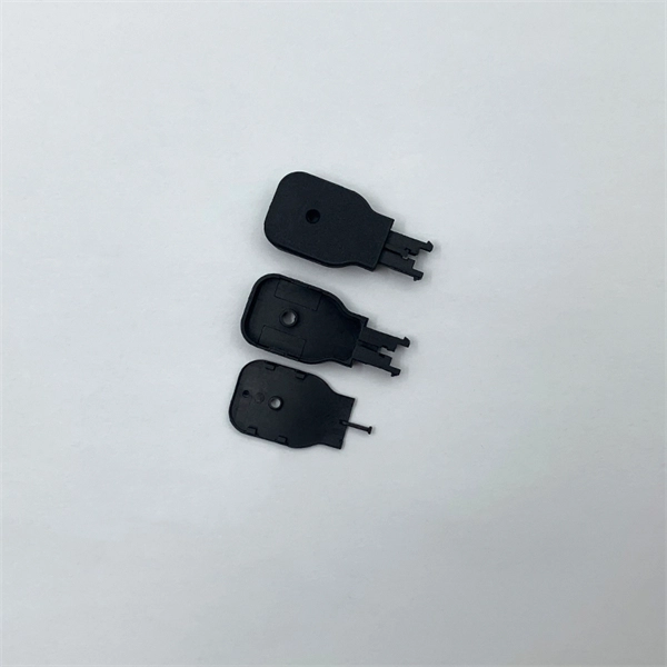
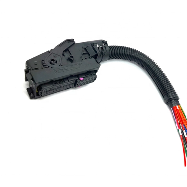
DISTRIBUTION BOX
Each DISTRIBUTION BOX and controller must be grounded. On the US market, a 5.26 mm 2 (10 AWG) ground wire must be used, and in all other markets a 6 mm 2 must be used.
Substation Components—Part 8: Grounding/Earthing Systems
This article examines the purpose of substation grounding, outlines the IEEE Std 80 design approach with emphasis on step and touch potential limits, discusses common grounding
Practical steps in the design of a substation grounding
Substation grounding provides a means of discharging and de-energizing equipment in order to proceed with maintenance on the equipment. It

Grounding Practices in Power Distribution Systems
Electrode Placement: In order to maximize the performance of the grounding system, it is recommended that grounding electrodes, which include rods and plates, be strategically placed around the
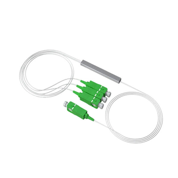
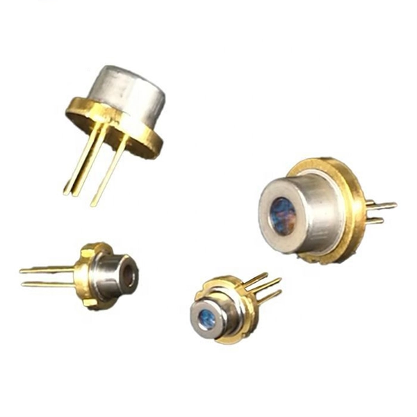
Optical Power Meters & Sources
High-precision power meters (Ge/InGaAs) and stabilized light sources for insertion loss and return loss testing.
OTDR & Fiber Characterization
Full-featured OTDR, fiber OTDR testers, and modular OTDR test modules for network deployment and troubleshooting.
OSA & Eye Diagram Analyzer
High-resolution OSA for DWDM and eye diagram testers for signal integrity validation.
BERT & Endface Inspection
BERT up to 800G, fiber endface inspection probes, and extinction ratio meters for comprehensive testing.