
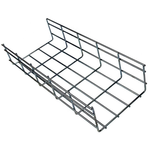
Tray Cable
At the vertical drops, a #3 insulated wire is split bolted onto the #3/0 and run with the tray cable in each separate conduit down to the panel. In the panel: you now have 2x #3 ground wires,
Practices for grounding and bonding of cable trays
In addition to providing an electrical connection between the cable tray sections and the EGC, the grounding clamp mechanically anchors the EGC to the cable tray so that under fault current

Cable Tray Grounding: Electrical and Non-Power Conductors
A separate EGC should be bonded to the cable tray with a bonding / grounding clamp. A separate EGC is commonly selected when single conductor cables are used. Either alternative can
Practices for grounding and bonding of cable trays
If an EGC cable is installed in or on a cable tray, it should be bonded to each or alternate cable tray sections via grounding clamps (this is not required by the NEC® but it is a desirable practice)
Understanding Cable Tray Grounding: A Comprehensive Guide
This comprehensive guide delves into the complexities of cable tray grounding, offering in-depth insights into its importance, principles, design considerations, installation best practices, and
EGC Guidelines for Cable Tray Systems
The document provides details on requirements and best practices for each option to ensure cable tray systems are properly grounded according to the NEC for safety.
Earthing or Bonding a Metallic Cable Tray: What the
If you must earth a tray for functional reasons (static discharge, RFI), do it at one end only. Bonding both ends can form a loop, increasing magnetic
Cable Tray Grounding Wire: What You Need to Know
Discover the best practices for Cable Tray Grounding Wire installation. Learn key requirements, safety tips, and material choices to ensure a grounding system.
Earthing or Bonding a Metallic Cable Tray: What the Regs Really Say
If you must earth a tray for functional reasons (static discharge, RFI), do it at one end only. Bonding both ends can form a loop, increasing magnetic coupling and nuisance RCD trips.
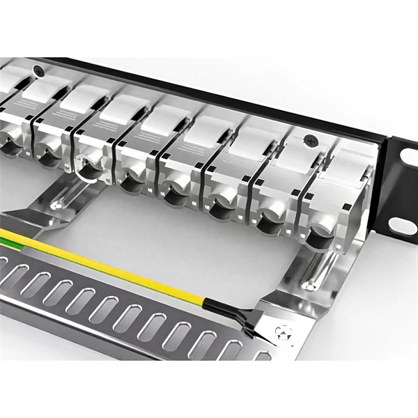
Grounding & Bonding Connectors
Cables must be secured to the cable tray prior to and after the transition, and protected by guarding or location. The electrical connection between sections can be maintained with bonding jumpers or a
Understanding Cable Tray Grounding: A
This comprehensive guide delves into the complexities of cable tray grounding, offering in-depth insights into its importance, principles, design
Grounding & Bonding Systems Guide | Winnie Industries
Grounding and bonding are the structural core of a compliant, resilient installation. This guide breaks down the hardware, standards, and field methods that ensure continuity—from UL
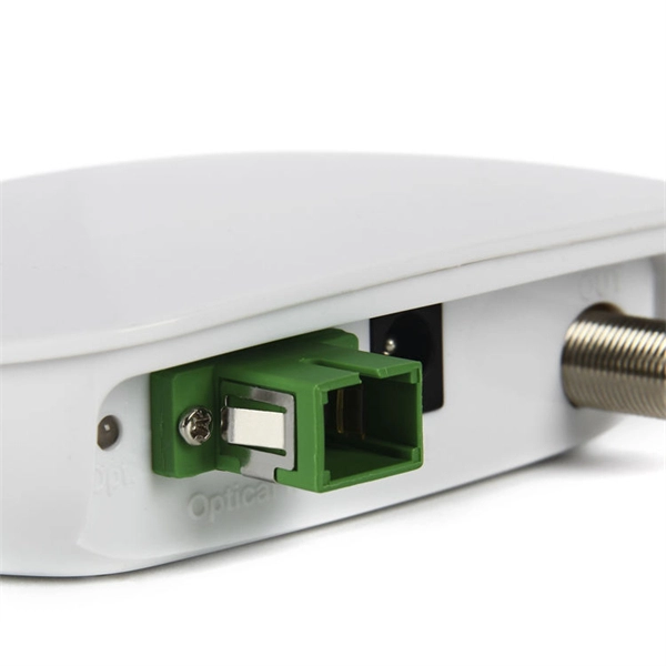
Optical Power Meters & Sources
High-precision power meters (Ge/InGaAs) and stabilized light sources for insertion loss and return loss testing.
OTDR & Fiber Characterization
Full-featured OTDR, fiber OTDR testers, and modular OTDR test modules for network deployment and troubleshooting.
OSA & Eye Diagram Analyzer
High-resolution OSA for DWDM and eye diagram testers for signal integrity validation.
BERT & Endface Inspection
BERT up to 800G, fiber endface inspection probes, and extinction ratio meters for comprehensive testing.