Bonding and Grounding wire mesh cable tray.
Cable tray sections, fittings, and connected raceways are bonded in accordance with 250.96, using bolted mechanical connectors or bonding jumpers sized and installed in accordance with 250.102.

Practices for grounding and bonding of cable trays
If an EGC cable is installed in or on a cable tray, it should be bonded to each or alternate cable tray sections via grounding clamps (this is not required by the NEC® but it is a desirable practice).
CABLE TRAY SYSTEMS GUIDE
Some applications may require the cable tray to support the weight of a single, dead object in addition to the cable loads. Specifications typically require this to be applied at the midpoint of the span between

Cable tray bonding | Information by Electrical Professionals for
(A) General. Metal raceways, cable trays, cable armor, cable sheath, enclosures, frames, fittings, and other metal non– current-carrying parts that are to serve as equipment grounding
DESIGN AND INSTALLATION OF CROSS-BONDING OF
To organize cross-bonding (Fig.1), the cable line is divided into a multiple of three number of sections of approximately equal length. At the junctions of sections, special cable joints are installed with outputs
Bonding and Grounding
Cable trays are designed and manufactured to support specific wiring methods, as identified in 392.10 (A). Metal cable trays can be used as EGCs where the conditions of 392.60 are met.
B-Line series Cable Tray Design Considerations
Our wind certification report provides you with list of acceptable B-Line series cable tray supports, fittings and covers based off of the environmental conditions, cable loading, and type of cable tray in your
Equipment Grounding Conductors for Cable Tray Systems
It is not necessary to apply conductive compound on the standard cable tray splice plate connections or to install bonding jumpers across the standard cable tray splice plate connections for aluminum or
Grounding & Bonding Connectors
Cables must be secured to the cable tray prior to and after the transition, and protected by guarding or location. The electrical connection between sections can be maintained with bonding jumpers or a

Cable Tray Technical Guide A practical guide to product selection
The choice of method should be discussed with a local inspector. The best decision may be to extend only the cables, creating a discontinuity in the cable tray.
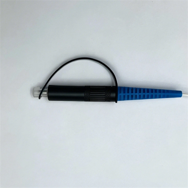
Optical Power Meters & Sources
High-precision power meters (Ge/InGaAs) and stabilized light sources for insertion loss and return loss testing.
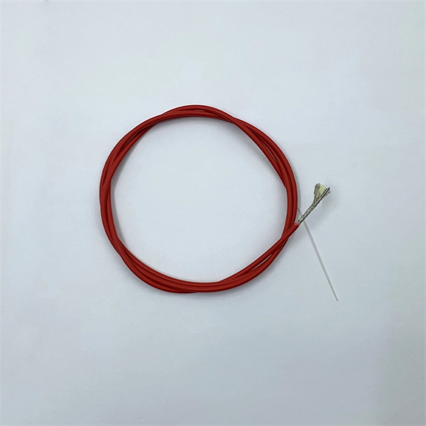
OTDR & Fiber Characterization
Full-featured OTDR, fiber OTDR testers, and modular OTDR test modules for network deployment and troubleshooting.
OSA & Eye Diagram Analyzer
High-resolution OSA for DWDM and eye diagram testers for signal integrity validation.
BERT & Endface Inspection
BERT up to 800G, fiber endface inspection probes, and extinction ratio meters for comprehensive testing.