Distribution System Grounding
IEEE C62.92.5 Guide for the Application of Neutral Grounding in Electrical Utility Systems, Part IV – Distribution. The guide deals with the neutral grounding of single‐ and three‐phase ac utility primary
How to Design System Grounding in Low Voltage Electrical Systems
LV system grounding is defined by the grounding mode of the MV/LV transformer secondary and the method of grounding the installation frames. Therefore, identification of the system types is defined
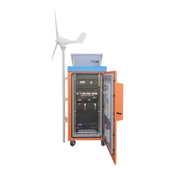
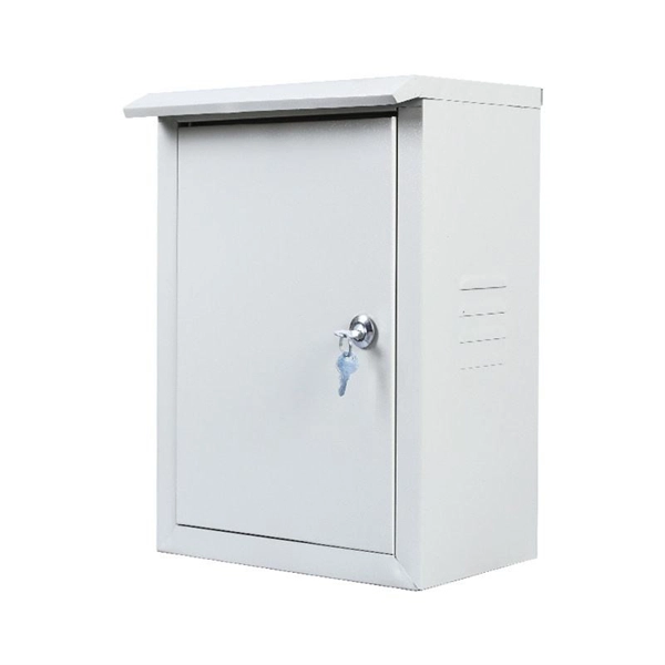
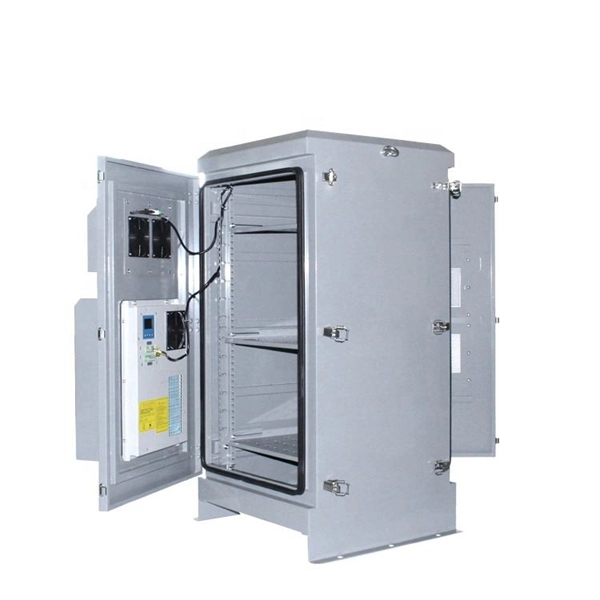
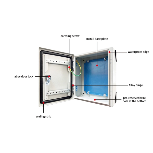
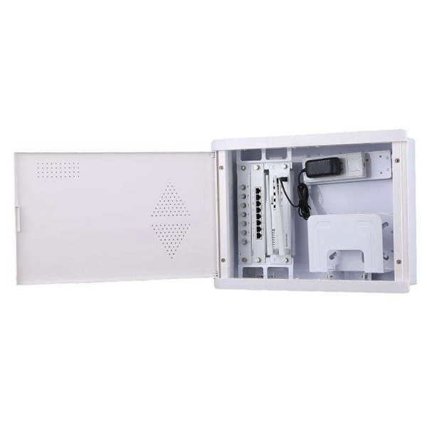
DISTRIBUTION BOX
Each DISTRIBUTION BOX and controller must be grounded. On the US market, a 5.26 mm 2 (10 AWG) ground wire must be used, and in all other markets a 6 mm 2 must be used.
Power Distribution Systems
One of the key tools in developing and documenting an electrical power system is the System One-Line (also called a Single Line Diagram). This drawing starts with the incoming power source from the

CYPELEC Distribution
Grounding system diagram The "Grounding" section of the main toolbar contains the tools for representing grounding systems in the building''s geometric model: The grounding systems that can

Distribution System Neutral Grounding Methods and Transformer
This report is intended to be a primer that illustrates the fundamentals of neutral grounding and transformer winding configuration as they relate to distribution system protection.
System Grounding
The topic of system grounding is extremely important, as it affects the susceptibility of the system to voltage transients, determines the types of loads the system can accommodate, and helps to
High Resistance Grounding (HRG) low-voltage design guide
To add high-resistance grounding to a wye-connected system, resistors are placed in series with the neutral-to-ground connection of the power source. The resistors are chosen to limit the current to a
Primary Service Standards
These also include one-line, three-line diagram, plan details of switchgear installation, and grounding system.
Grounding Practices in Power Distribution Systems
The installation of grounding methods for transmission lines is absolutely necessary in order to guarantee the safety, dependability, and effectiveness of power distribution systems.
10-15-* Grounding with a meter base on the supply side of service
Where the consumer''s service has a single meter base and service box, the Ontario Electrical Safety Code (OESC) permits the grounding connection at the meter base or at the service box as per
Optical Power Meters & Sources
High-precision power meters (Ge/InGaAs) and stabilized light sources for insertion loss and return loss testing.
OTDR & Fiber Characterization
Full-featured OTDR, fiber OTDR testers, and modular OTDR test modules for network deployment and troubleshooting.
OSA & Eye Diagram Analyzer
High-resolution OSA for DWDM and eye diagram testers for signal integrity validation.
BERT & Endface Inspection
BERT up to 800G, fiber endface inspection probes, and extinction ratio meters for comprehensive testing.